In a series L−C−R circuit, currenrt in the circuit is 11A when the applied voltage is 220V. voltage across the caspcitor is 200V. If the value of resistor is 20Ω, then the voltage across the unknown inductor is
zero
200V
20V
none of these
The correct Answer is:B
i=VR i.e.circuit is in resonance. Hence,
Topper's Solved these Questions
- ALTERNATING CURRENTBook:DC PANDEYChapter:ALTERNATING CURRENTExercise:Level- 2More Than One Correct
Explore 8 Videos
- ALTERNATING CURRENTBook:DC PANDEYChapter:ALTERNATING CURRENTExercise:Level 2 Comprehension
Explore 6 Videos
- ALTERNATING CURRENTBook:DC PANDEYChapter:ALTERNATING CURRENTExercise:Level - 1 Subjective
Explore 6 Videos
- ATOMSBook:DC PANDEYChapter:ATOMSExercise:MEDICAL ENTRANCES GALLERY
Explore 42 Videos
Similar Questions
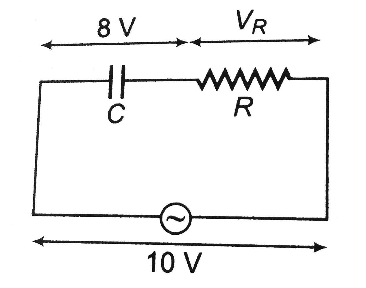
In a series CR circuit shown in figure,the applied voltage is 10V and the voltage across capacitor is found to be 8V
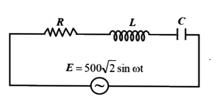
View SolutionIn the series L−C−R circuit shown in the figure, the rms voltage across the resistor and inductor are 400 V and 700 V respectively. If the applied voltage is E=500√2sin(ωt), then the peak voltage across the capacitor is

View Solution
Knowledge Check
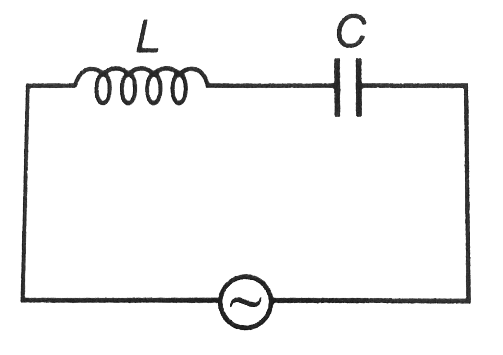
In a series L−C circuit, the applied voltage is V0. if omega is very low, then the voltage drop across the inductor VL and capacitor VC are
 .AVL=V02,VC=V02BVL=0,VC=V0CVL=V0,VC=0DVL=−VC=V02
In an L-C-R circuit, if V is the effective value of the applied voltage VR is the voltage across R, VL is the effective voltage across L, VC is the effective voltage across C, then
AV=VR+VL+VCBV2=V2R+V2L+V2CCV2=V2R+(VL−VC)2DV2=V2L+(VR−VC)2In an LCR series circuit, the voltage across each of the components L,C and R is 20 V. The voltage across the L-C combination will be
A20 VB40 VCzeroD20√2V
An ac source of 50 V (r.m.s value) is connected across a series R - C circuit. If the r.m.s voltage across the resistor is 40 V, then the r.m.s voltage across the capacitor is
View SolutionIn a series C−R circuit shown in figureure, the applied voltage is 10V and the voltage across capacitor is found to8V. The voltage across R, and the phase difference between current and the applied voltage will respectively be
 .
.
View SolutionIn series resonant circuit, at resonance the phase difference between the voltage across inductor and voltage across condenser is
View SolutionIn series LCR circuit, the phase difference between voltage across L and voltage across C is
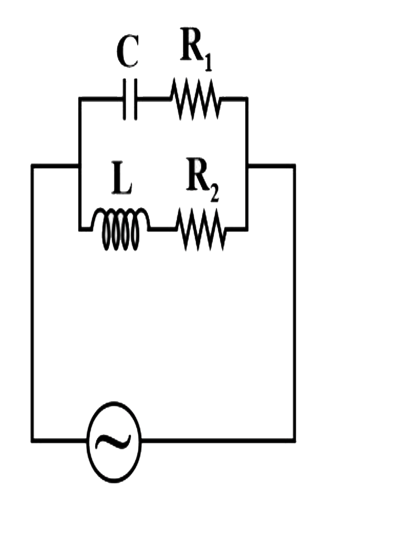
View SolutionIn the given circuit the R.M.S values of voltages across the capacitor C, inductor L and resistor R1 are 12V, 10V and 5 V respectively. Then the peak voltage across R2 is

View Solution
