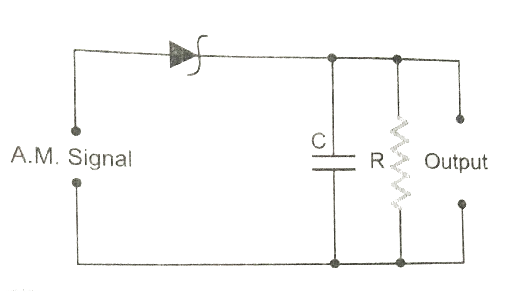
Fig. 10 (CF).1 is the circuit diagram of an AM demodulator. For good demodulation of AM signal of carrier frequency f, the value of RC should be

RC=1/f
RC<1/f
RC≥1/f
RC>>1/f
The correct Answer is:D
For good demdulation.
1f<<RC.orRC>>1f.
Topper's Solved these Questions
Similar Questions
A message signal of frequency 10 kHz and peak voltage of 10 volts is used to modulate a carrier of frequency 1 MHz and peak voltage of 20 volts. The side bands are 10 10 kHz and _________________kHz.
View SolutionA bat moving at 10ms−1 towards a wall sends a sound signal of 8000 Hz towards it. On reflection it hears a sound of frequency f. The value of g in Hz is close to (speed to sound =320ms−1) :-
View Solution
Knowledge Check
- Question 1 - Select One
Fig. 10 (CF).1 is the circuit diagram of an AM demondulator. For good demodulation of AM signal of carrier frequency f, the value of RC should be
 ARC=1/fBRC<1/fCRC≤1/fDRC>>1/f
 - Question 2 - Select One
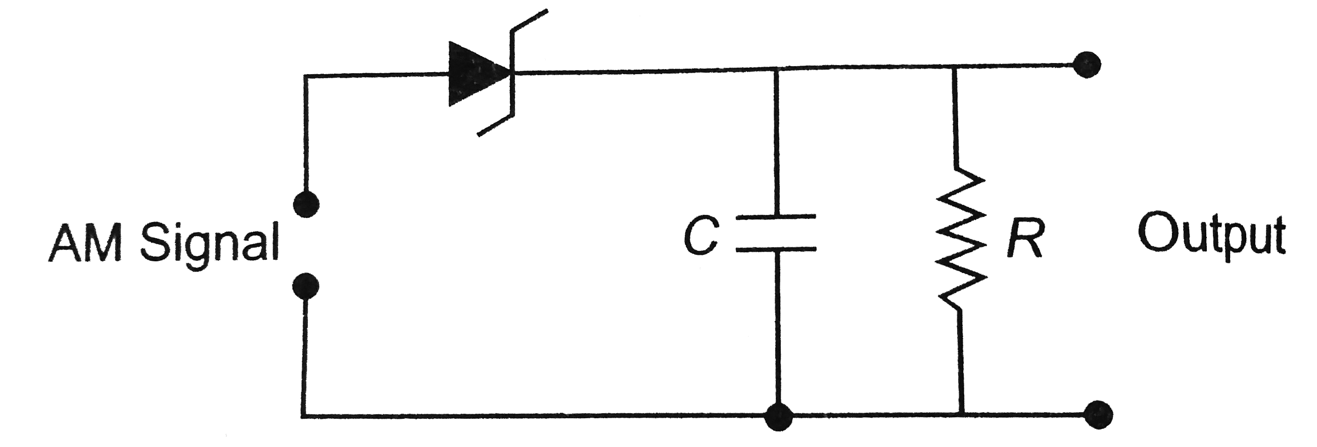
Given below a circuit diagram of an AM demodulator.

For good demodulation of AM signal of carrier frequency f, the value of RC should be:ARC=1fBRC<1fCRC≥1fDRC>>1f - Question 3 - Select One
A message signal m(t)=4cos2000πt modulates the carrier C(t)=cos2πfct where fc=1MHz to produce an AM signal. For demodulation using envelope detector the time constant RC should satisfy
A0.5ms<RC<1msB1μs<<RC<<1msCRC>>1μsDRC>>1μs
Both amplitude modulation (AM) and frequency modulation (FM) are used for radio broadcasting. The amplitude of the high frequency carrier wave is varied or modulated in accordance with the variations in the amplitude of the audio signals that are to be transmitted, in te process of amplitude modulation in frequency modulation te amplitude of the carrier remains constant but its frequency is varied inn accordance withh the audio signal. Reception with AM signals is in general is affected by interference of various kinds ad elaborated equipment is required for FM broadcast.
A radio frequency carrier wave can be modulated using a-View SolutionBoth amplitude modulation (AM) and frequency modulation (FM) are used for radio broadcasting. The amplitude of the high frequency carrier wave is varied or modulated in accordance with the variations in the amplitude of the audio signals that are to be transmitted, in te process of amplitude modulation in frequency modulation te amplitude of the carrier remains constant but its frequency is varied inn accordance withh the audio signal. Reception with AM signals is in general is affected by interference of various kinds ad elaborated equipment is required for FM broadcast.
In india the radio signals are boarcast using-View SolutionBoth amplitude modulation (AM) and frequency modulation (FM) are used for radio broadcasting. The amplitude of the high frequency carrier wave is varied or modulated in accordance with the variations in the amplitude of the audio signals that are to be transmitted, in te process of amplitude modulation in frequency modulation te amplitude of the carrier remains constant but its frequency is varied inn accordance withh the audio signal. Reception with AM signals is in general is affected by interference of various kinds ad elaborated equipment is required for FM broadcast.
The rangeof a transmitter isView SolutionA carrier frequency of 1 MHz and peak value of 10 V is amplitude modulated with a signal frequency of 10 KHz with peak value of 0.5 V. What are the values of the modulation index and the side band frequencies ?
View SolutionIn an A.C. circuit, a capacitor of 1μF value is connected to a source of frequency 1000 rad/sec. The value of capacitive reactance will be –
View Solution

