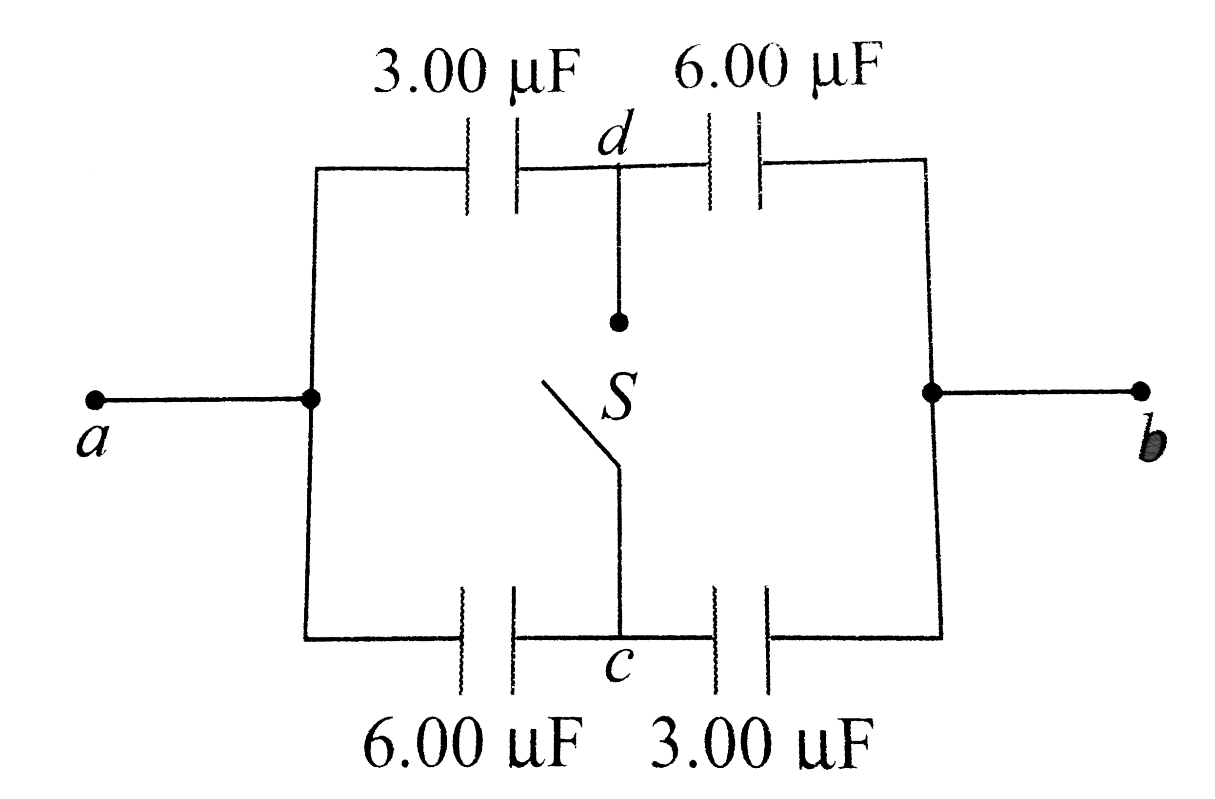
The capacitors in are initially uncharged and are connected as in the diagram with switch S open. The applied potential difference is Vab=+360V.
 .
.
a. What is the potential difference Vcd
b What is the potential difference across each capacitor after switch S is closed?
c. How much charge will flow through the switch after it is closed?
The correct Answer is:a. 120V b. 18 Vc.540 muComC→D.
(a) Refer to
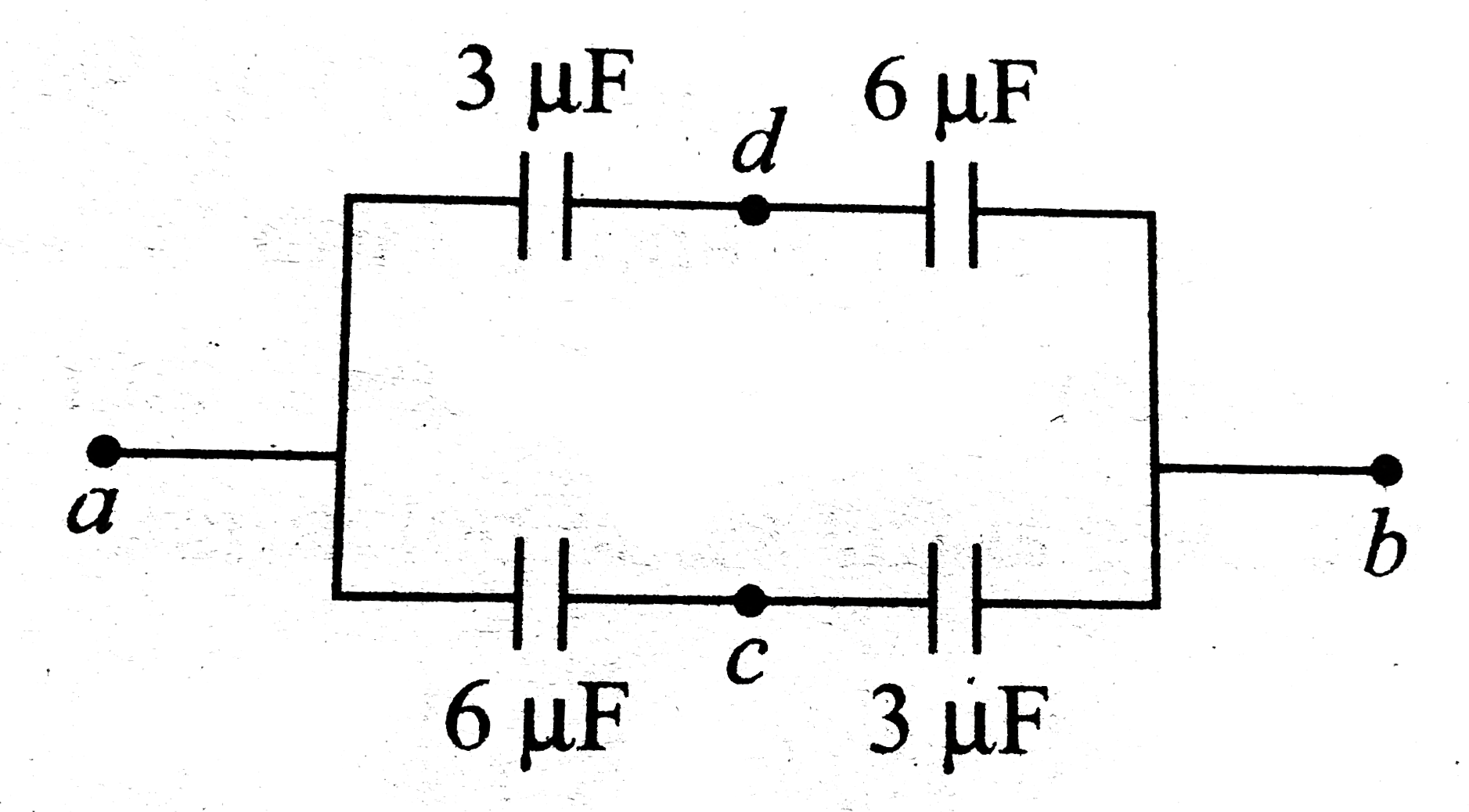
VaVd=66+3×360=240V
and Va−Vc=36+3×360=120V
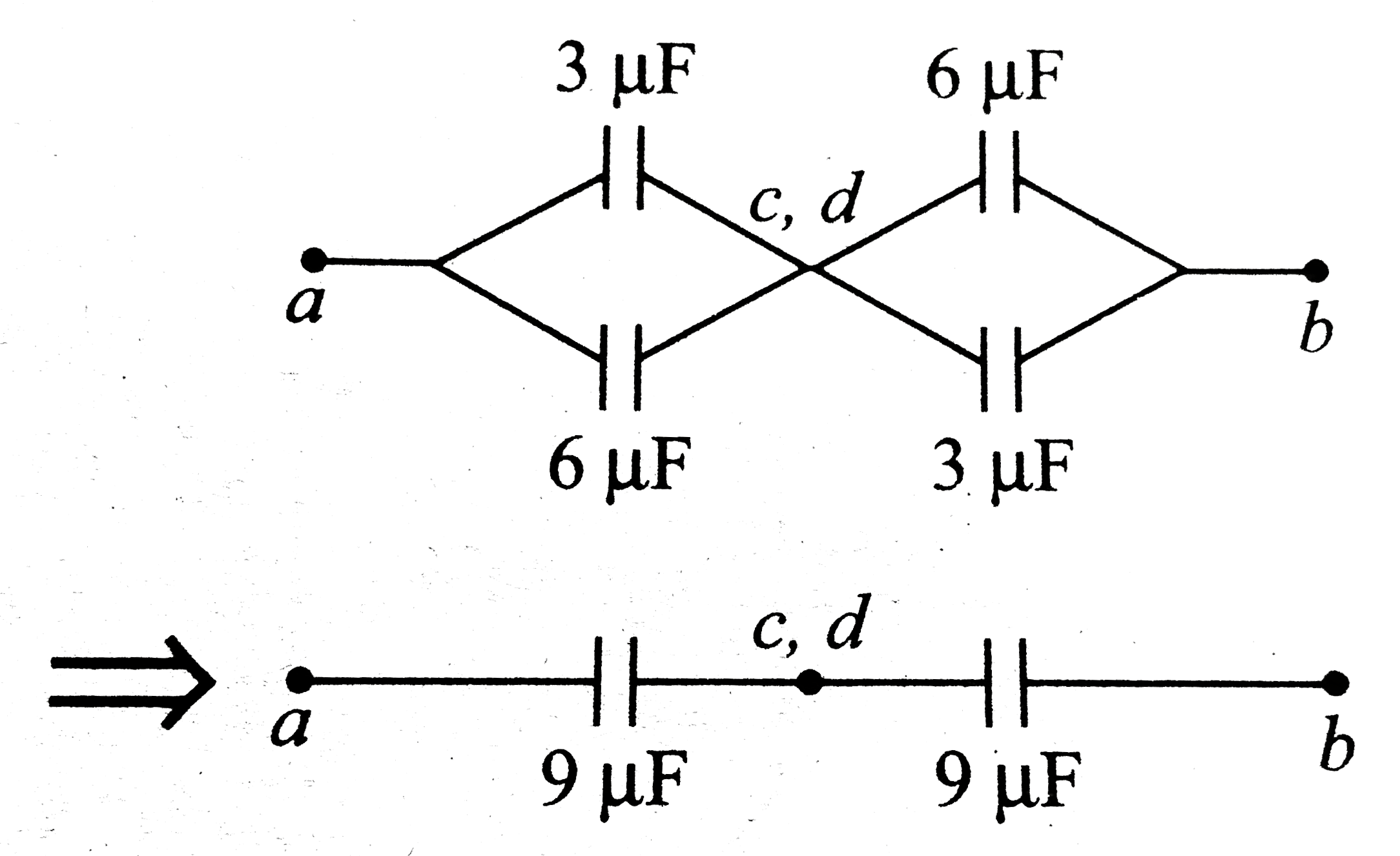
(b) Refer to
 .
.
Va−Vc=Va−Vd=Vd−Vb=Vc−Vb
=3602=180V
That is, potential across each capacitor is 180V
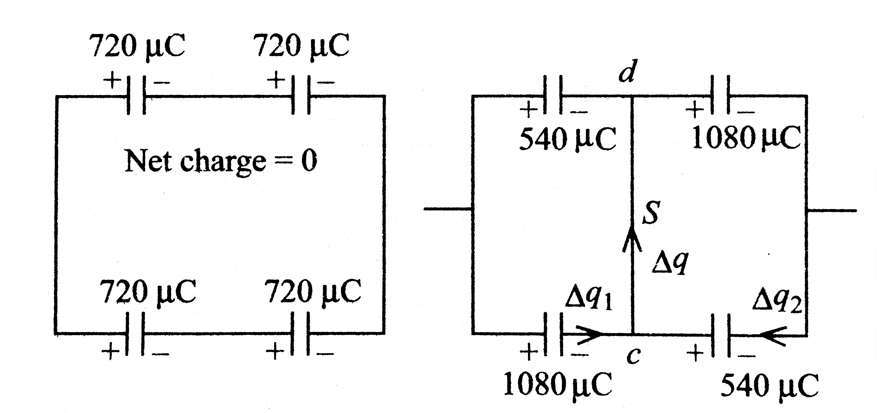
c. Charge flowing after the switch is closed:
Δq1=1080−720=360μC
Δq2=720−540=180μC
Now,
Δq=Δq1+Δq2=360+180=540μC
Hence, charge of 540μC flows from c and d after closing the switch.
 .
.
Topper's Solved these Questions
- CAPACITOR AND CAPACITANCEBOOK - CENGAGE PHYSICSCHAPTER - CAPACITOR AND CAPACITANCEEXERCISE - Single Correct
49 Videos
- CAPACITOR AND CAPACITANCEBOOK - CENGAGE PHYSICSCHAPTER - CAPACITOR AND CAPACITANCEEXERCISE - Multile Correct
11 Videos
- CAPACITOR AND CAPACITANCEBOOK - CENGAGE PHYSICSCHAPTER - CAPACITOR AND CAPACITANCEEXERCISE - Exercise 4.2
32 Videos
- ATOMSBOOK - CENGAGE PHYSICSCHAPTER - ATOMSEXERCISE - QUESTION BANK
40 Videos
- CENGAGE PHYSICS DPPBOOK - CENGAGE PHYSICSCHAPTER - CENGAGE PHYSICS DPPEXERCISE - subjective type
51 Videos
Similar Questions
The capacitors in are initially uncharged and are connected as in the diagram with switch S open. The applied potential difference is Vab=+360V.
 .
.
a. What is the potential difference Vcd
b What is the potential difference across each capacitor after switch S is closed?
c. How much charge will flow through the switch after it is closed?
View SolutionThe capacitors in are initially uncharged and are cannected as in the diagram with switch S open. The applied potential differnce is Vab=+360V.
 .
.
a. What is the potential differnce Vcd
b What is the potential deffernce across each capacitor afrer switch S is closed?
c. How much charge will flow through the awitch after it is closed?
View Solution
Knowledge Check
The two capacitors in the circuit shown in figure are initially uncharged and then connected as shown and switch is closed. What is the potential difference across 3μF capacitor?
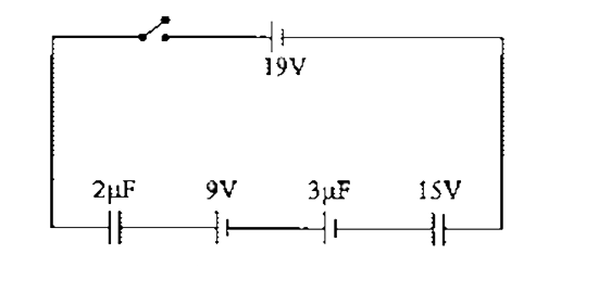 A30VB10VC25VDNone of these
Four capacitors of capacitance 10μF and a battery of 200V are arranged as shown. How much charge will flow through AB after the switch S is closed :
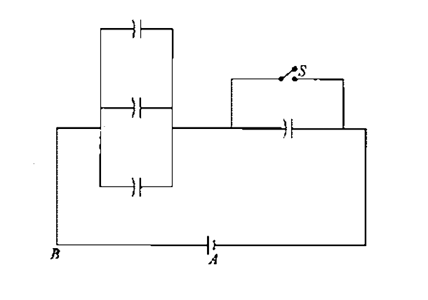 A6000μCB4500μCC3000μCD4000μC
The connections shown in figure are established with the switch S open. How much charge will flow through the switch if it is closed ?
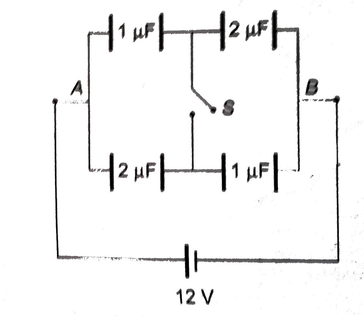 .
.
View Solution(i) What is the final potential (in V) of point b with respect to ground in steady state after switch S is closed ?
(ii) How much charge flows through switch S from b to a after it is closed in μC.
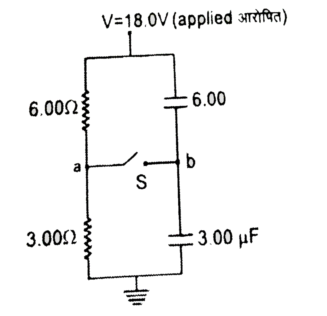
View Solution(i) What is the final potential (in V) of point b with respect to ground in steady state after switch S is closed ?
(ii) How much charge flows through switch S from b to a after it is closed in μC.

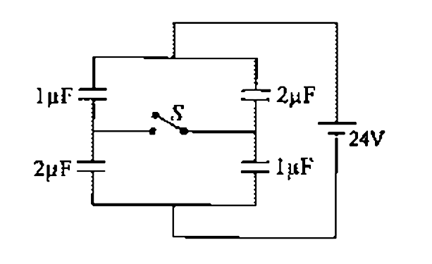
View SolutionFour uncharged capacitors are charged by 24V battery as shown in the figure. How much charge flows through switch S when it is closed?
View Solution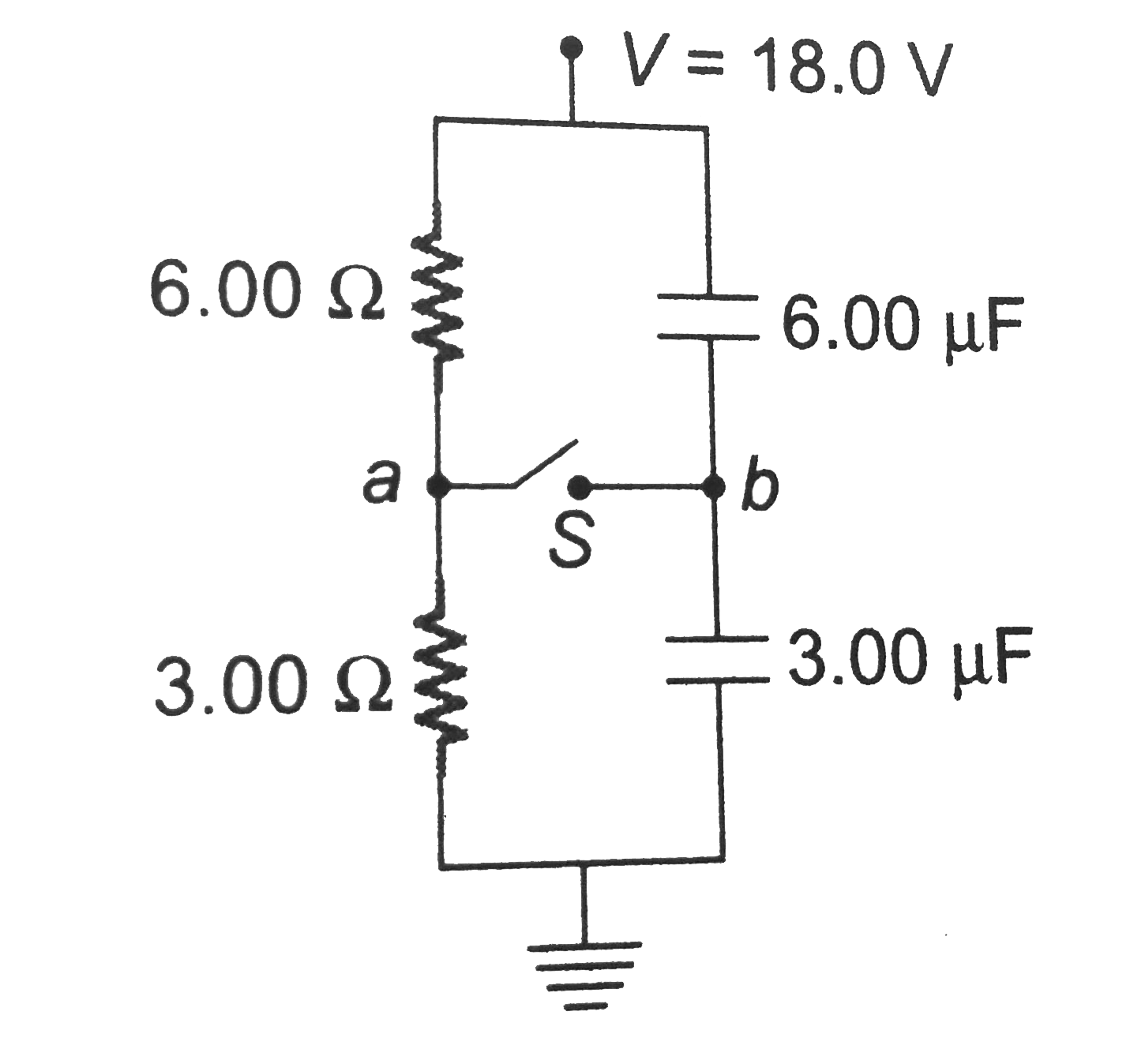
(a) What is the potential of point a with respect to point b in figure, when switch S is open?
(b) Which point, a or b, is at the higher potential?
(c) What is the final potential of point b with respect to ground when switch S is closed?
(d) How much charge flows through switch S when it is closed?
View Solution
(a) What is the potential of point a with respect to point b in figure, when switch S is open?
(b) Which point, a or b, is at the higher potential?
(c) What is the final potential of point b with respect to ground when switch S is closed?
(d) How much charge flows through switch S when it is closed?
View Solution
