In the circuit diagram shown in Fi,
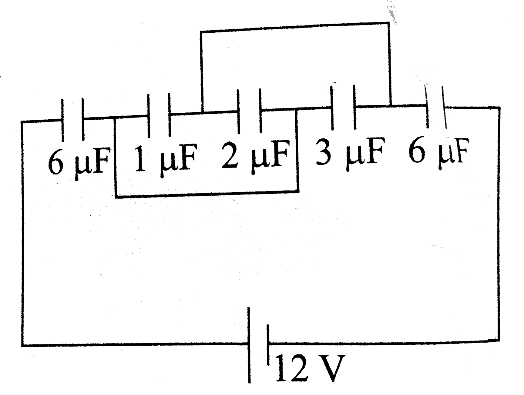 .
.
the charge on capacitor is
the charge on each capacitor is
the pottential drop across capacitor is .
the potential drop across is 4 V
The correct Answer is:A, C, D
Capacitors are in parallel, and their total capacitance is Thus, we have three capcitors in series, each of capacitance across the power supply. So potential drop across each is . So options and are correct. charge on capacitor is . So option is correct.
Charge on capacitor is . So option is wrong.
Thus, correct options are , and .
Topper's Solved these Questions
- CAPACITOR AND CAPACITANCEBOOK - CENGAGE PHYSICSCHAPTER - CAPACITOR AND CAPACITANCEEXERCISE - Comprhension
35 Videos
- CAPACITOR AND CAPACITANCEBOOK - CENGAGE PHYSICSCHAPTER - CAPACITOR AND CAPACITANCEEXERCISE - Integer
5 Videos
- CAPACITOR AND CAPACITANCEBOOK - CENGAGE PHYSICSCHAPTER - CAPACITOR AND CAPACITANCEEXERCISE - Single Correct
49 Videos
- ATOMSBOOK - CENGAGE PHYSICSCHAPTER - ATOMSEXERCISE - QUESTION BANK
40 Videos
- CENGAGE PHYSICS DPPBOOK - CENGAGE PHYSICSCHAPTER - CENGAGE PHYSICS DPPEXERCISE - subjective type
51 Videos
Similar Questions
Knowledge Check
In the circuit diagram shown in the adjoining figure, the resultant capacitance between P and Q is
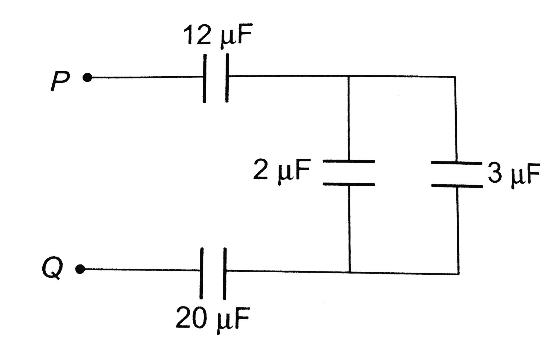 A47μFB3μFC60μFD10μF
Carefully study the circuit diagram shown and calculate the value of x.
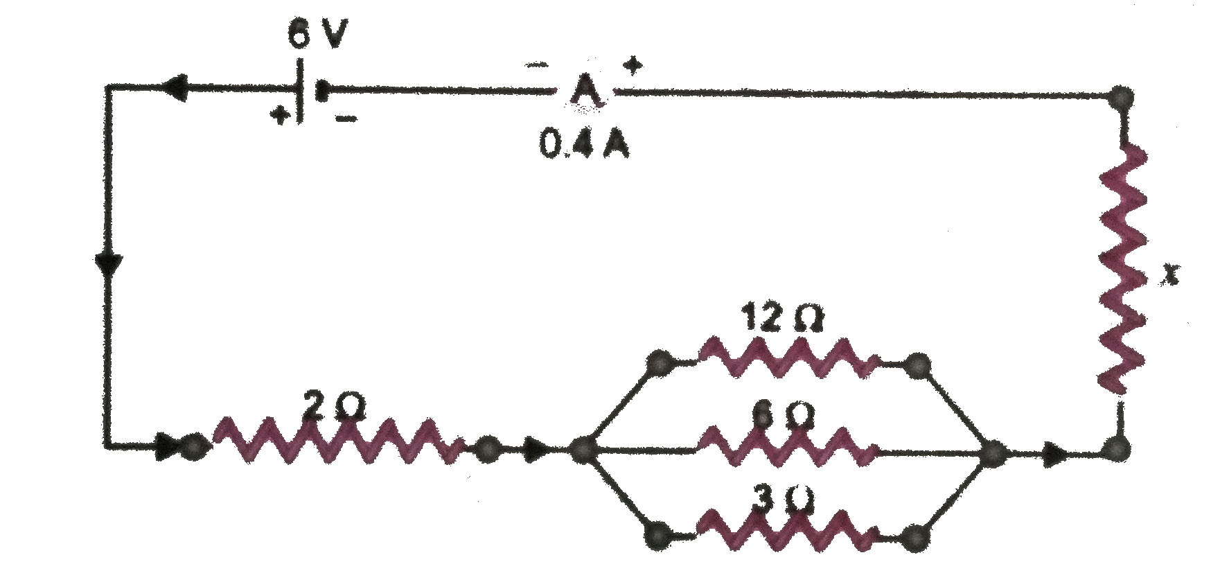 .A14.3 ohmB11.3 ohmC12 ohmD23.4 ohm
In the circuit shown
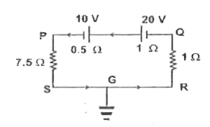 Athe potential at Πs−7.5VBthe potential at Qis−1VCthe potential at R is zeroDthe potential al S is zero
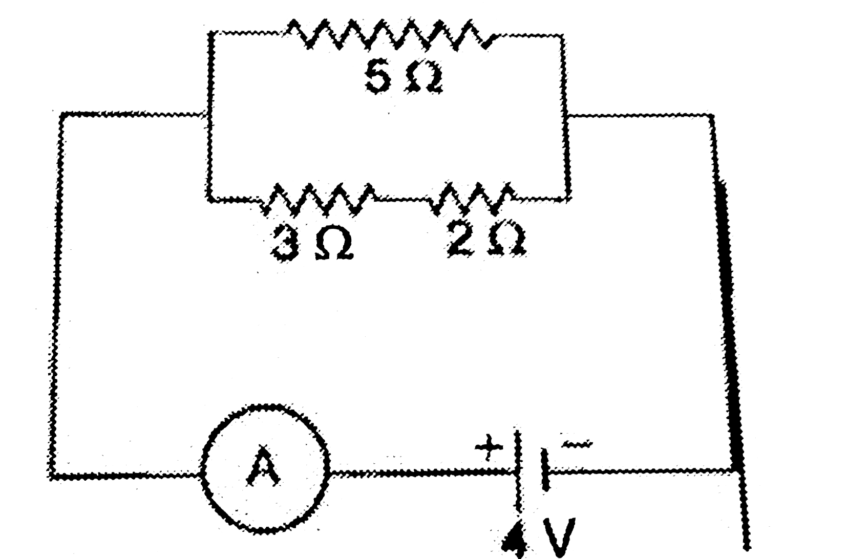
(a) With the help of a circuit diagram, obtain the relation for the equivalent resistance of two resistances connected in parallel.
(b) In the circuit diagram shown below, find:
(i) Total resistance.
(ii) Current shown by the ammeter A
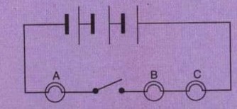
View SolutionIn the circuit diagram shown below :
Would any of the bulbs glow when the switch is in the 'off' position ?
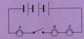
View SolutionIn the circuit diagram shown below :
What will be the order in which the bulbs A, B and C will glow when the switch is moved to the 'on' position ?
View SolutionIn the circuit diagram shown, all the capacitors are in μF. The equivalent capacitance between points A and Bis (in μF)
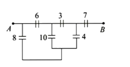
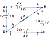
View SolutionCalculate the current through the resistace connected across MN and the current supplied by each of the batteries in the circuit diagram shown in
View Solution

