The capacitor shown in figure has been charged to a potential difference of volt, so that it carries a charge with both the switches remaining open. Switch is closed at . At switch is opened and is closed. Find the charge on the capacitor at .
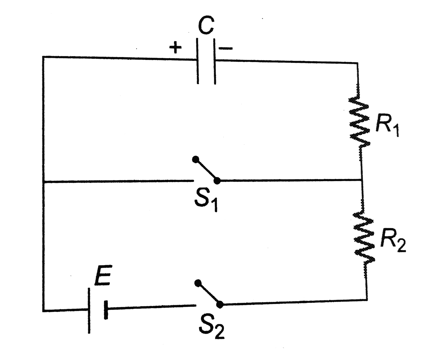
First, capacitor will discharge through
Now it will be charged through
Topper's Solved these Questions
- BOOK - CENGAGE PHYSICSCHAPTER - ELECTRIC CURRENT AND CIRCUITEXERCISE - Exercise 5.128videos
ELECTRIC CURRENT AND CIRCUIT
- BOOK - CENGAGE PHYSICSCHAPTER - ELECTRIC CURRENT AND CIRCUITEXERCISE - Exercise 5.250videos
ELECTRIC CURRENT AND CIRCUIT
- BOOK - CENGAGE PHYSICSCHAPTER - ELECTRIC CURRENT AND CIRCUITEXERCISE - Interger8videos
ELECTRIC CURRENT AND CIRCUIT
- BOOK - CENGAGE PHYSICSCHAPTER - ELECTRIC CURRENT & CIRCUITSEXERCISE - Kirchhoff s law and simple circuits15videos
ELECTRIC CURRENT & CIRCUITS
- BOOK - CENGAGE PHYSICSCHAPTER - ELECTRIC FLUX AND GAUSS LAWEXERCISE - MCQ s38videos
ELECTRIC FLUX AND GAUSS LAW
Similar Questions
At t =0 switch S1 is closed and remains closed for a long time and S2 remains open. Now S1 is opened and S2 is closed. Find out
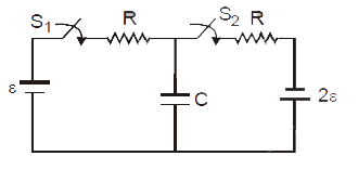
Charge on the capacitor long after that moment.View SolutionAt t =0 switch S1 is closed and remains closed for a long time and S2 remains open. Now S1 is opened and S2 is closed. Find out
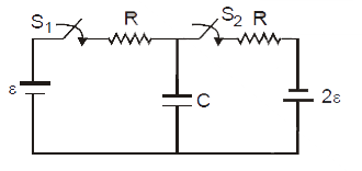
The current through the capacitor immediately after that momentView Solution
Knowledge Check
- Question 1 - Select One or More
Two capacitorsC1=4μFandC2=2μF are charged to same potential V = 500 Volt, but with opposite polarity as shown in the figure. The switches S1andS2are closed.
AThe potential difference across the two capacitors are same and is given by 500/3VBThe potential difference across the two capacitors are same and is given by 1000/3VCThe ratio of final energy to initial energy of the system is 1/9DThe ratio of final energy to initial energy of the system is 4/9 - Question 2 - Select One
In the circuit in Fig. switch S1 was closed for a long time . At time t=0 the switch is opened.
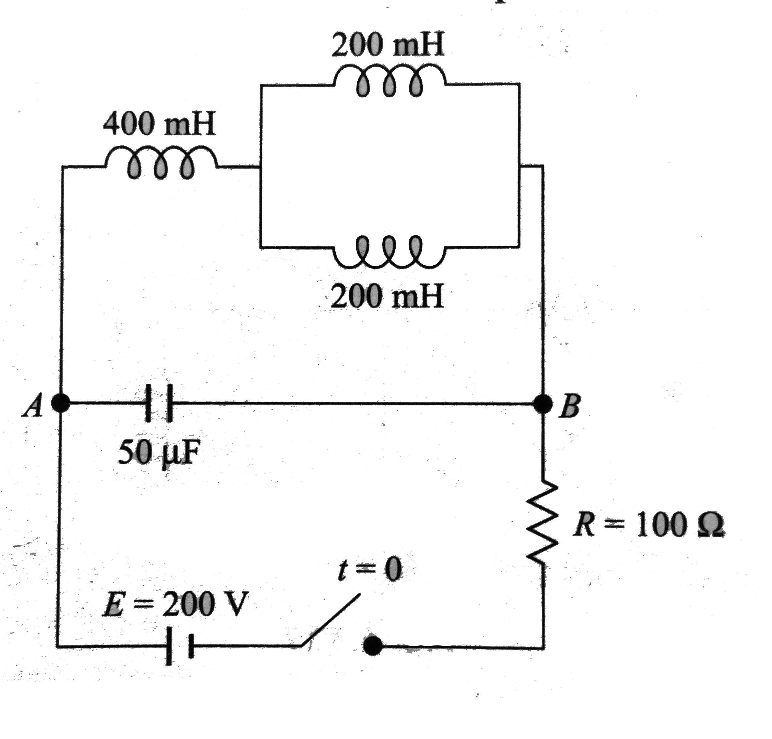
Find the angular frequency of oscillation of the charge on the capacitor.A100rads−1B200rads−1C300rads−1sD400rads−1 - Question 3 - Select One or More
Two capacitors C1 and C2 are charged to same potential V, but with opposite polarity as shown in the figure. The switches S1 and S2 are then closed
 APotential difference across two capacitors are same and is given by (C1−C2)VC1+C2BPotential difference across two capacitors are same and is given by (C1+C2C1−C2)VCRatio of final energy to initial energy of the system is given by (C1−C2)2(C1+C2)2DRatio of final energy to initial energy of the system is given by (C1)2(C1+C2)2
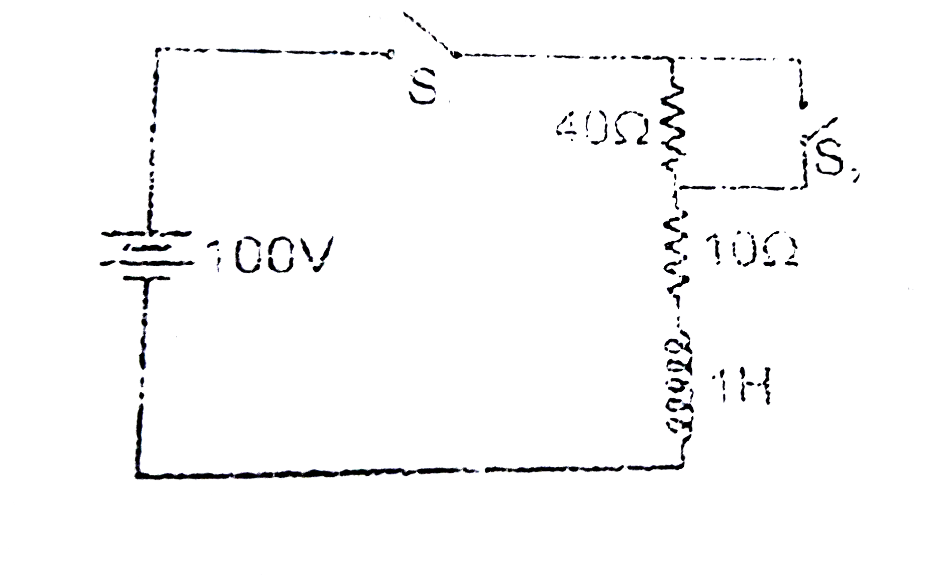
In the circuit diagram shown in the figure the switches S1 and S2 are closed at time t=0.After time t=(0.1)ln2sec, switch S2 is opened.The current in the circuit at time t=0.2n2sec is equal to x32amp.Find out value of x.
 View Solution
A capacitor of capacitance C1 is charged to a potential difference V and then connected with an uncharged capacitor of capacitance C2 a resistance R. The switch is closed at t = 0. Choose the correct option(s):
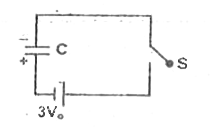
View SolutionIn the circuit shown in the figure, the capacitor C is charged to a potential Vo. The heat generated in the circuit when the switch S is closed, is
View Solutionn the circuit shown in the figure, the capacitor C is charged to a potential Vo The heat generated and charge flow, in the circuit to when the switch S is closed, is
 View Solution
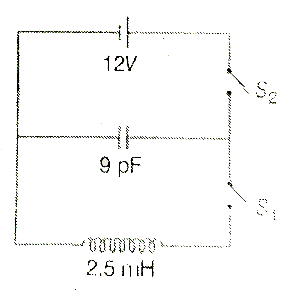
In the circuit shown, the capacitor initially charged with a 12V batteryy, when switch S1 is open and switch S2 is closed. The maximum value of current in the circuit when S2 is opened and S2 is closed is
 View Solution

