For the circuit arrangement shown in fig.
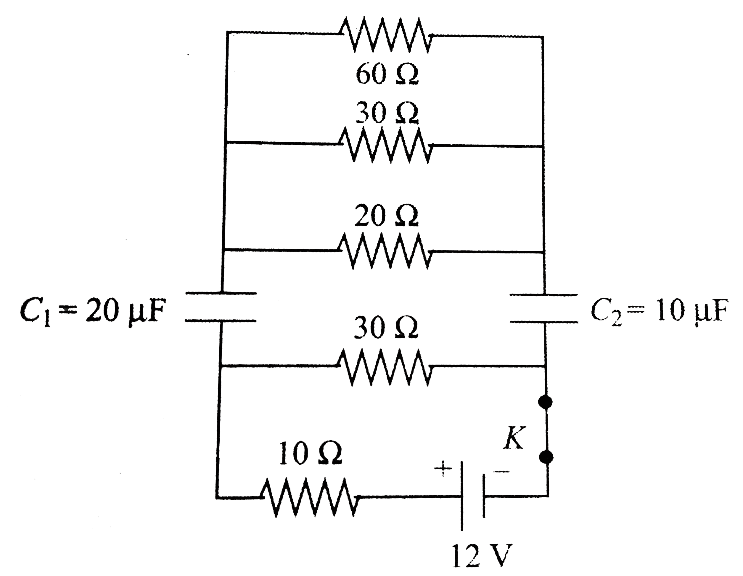
a. Find the potentail difference across each capacitor in the steady - state condition.
b. Find the current through the 60Ω resistor just after the instant when the key K is opened.
Video Solution
Text Solution
In the steady state, no current passes through upper three
resistors. So I=1210+30=0.3A
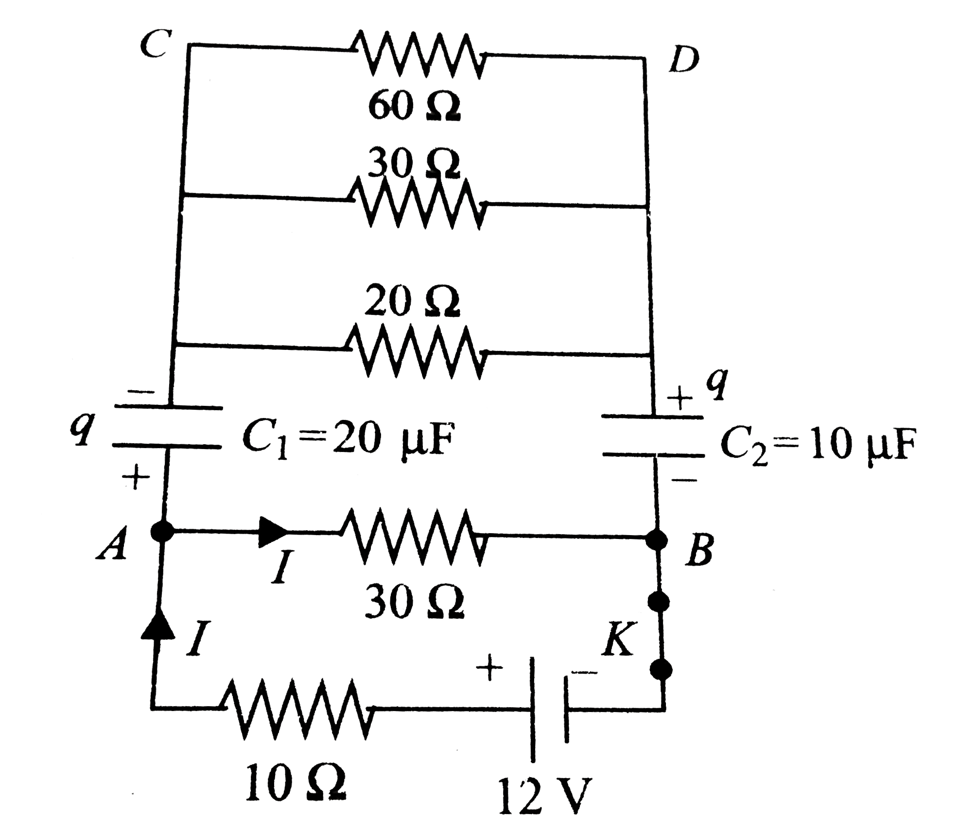
Potential difference between A and B is V=30×0.3=9V.
Now in loop ACDBA:
qC1+qC2=9
or q20+q10=9orq=60μC
a. Potential difference across C1:
V1=qC1=6020=3V
Potential difference across C2:
V2=qC2=6010=6V
b. After K is opened, 12 V will be out of circuit , and capacitors
will act as batteries as shown in fig.

Now one can find I1=0.0375A.
|
Updated on:21/07/2023
Topper's Solved these Questions
- BOOK - CENGAGE PHYSICSCHAPTER - ELECTRIC CURRENT AND CIRCUITEXERCISE - Single Correct72videos
ELECTRIC CURRENT AND CIRCUIT
- BOOK - CENGAGE PHYSICSCHAPTER - ELECTRIC CURRENT AND CIRCUITEXERCISE - Multiple Correct16videos
ELECTRIC CURRENT AND CIRCUIT
- BOOK - CENGAGE PHYSICSCHAPTER - ELECTRIC CURRENT AND CIRCUITEXERCISE - Exercise 5.250videos
ELECTRIC CURRENT AND CIRCUIT
- BOOK - CENGAGE PHYSICSCHAPTER - ELECTRIC CURRENT & CIRCUITSEXERCISE - Kirchhoff s law and simple circuits15videos
ELECTRIC CURRENT & CIRCUITS
- BOOK - CENGAGE PHYSICSCHAPTER - ELECTRIC FLUX AND GAUSS LAWEXERCISE - MCQ s38videos
ELECTRIC FLUX AND GAUSS LAW
Similar Questions
Knowledge Check
- Question 1 - Select One
In the fig. shown the circuit is in steady state.
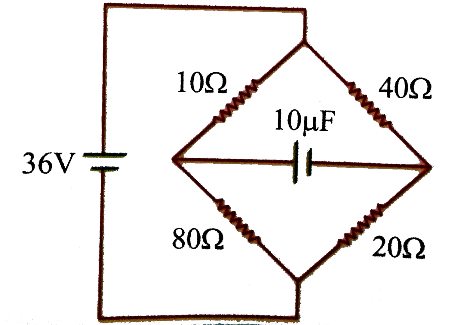
what is the potential difference across the capacitor in steady state ?A5 VB10 VC20 VD40 V - Question 2 - Select One
Refer to Fig. 7.49.
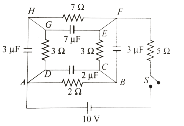
Long time after closing the switch , find the current through the 5Ω resistor.A45AB25AC65AD85A - Question 3 - Select One
In the given circuit the potential difference across the capacitor is 12V in steady state. Each resistor have 3Ω resistance. The emf of the ideal battery is
 A15VB9VC12VD24V
Consider the circuit shown in figure. Find the current through the 10Ω resistor when the switch S is (a) opened (b) closed.
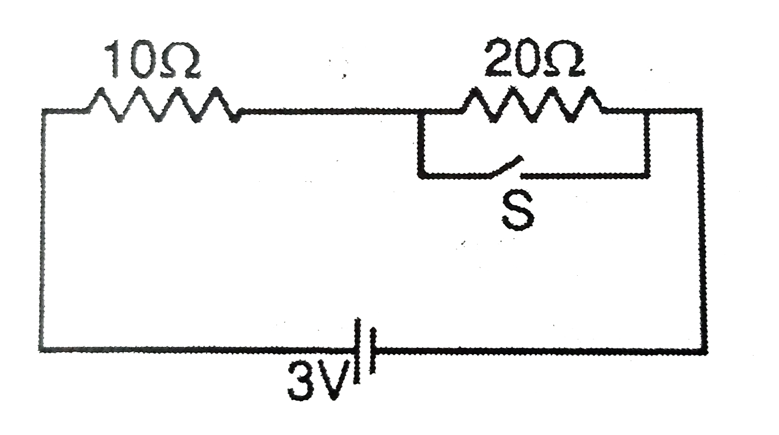 View Solution
In a circuit shown in fig find the potentail difference between the left and right plates of each capacitor.
 View Solution
Consider the circuit shown in figure.Find the current through the10(Ω)resistor when the switch S is (a)open (b)closed .
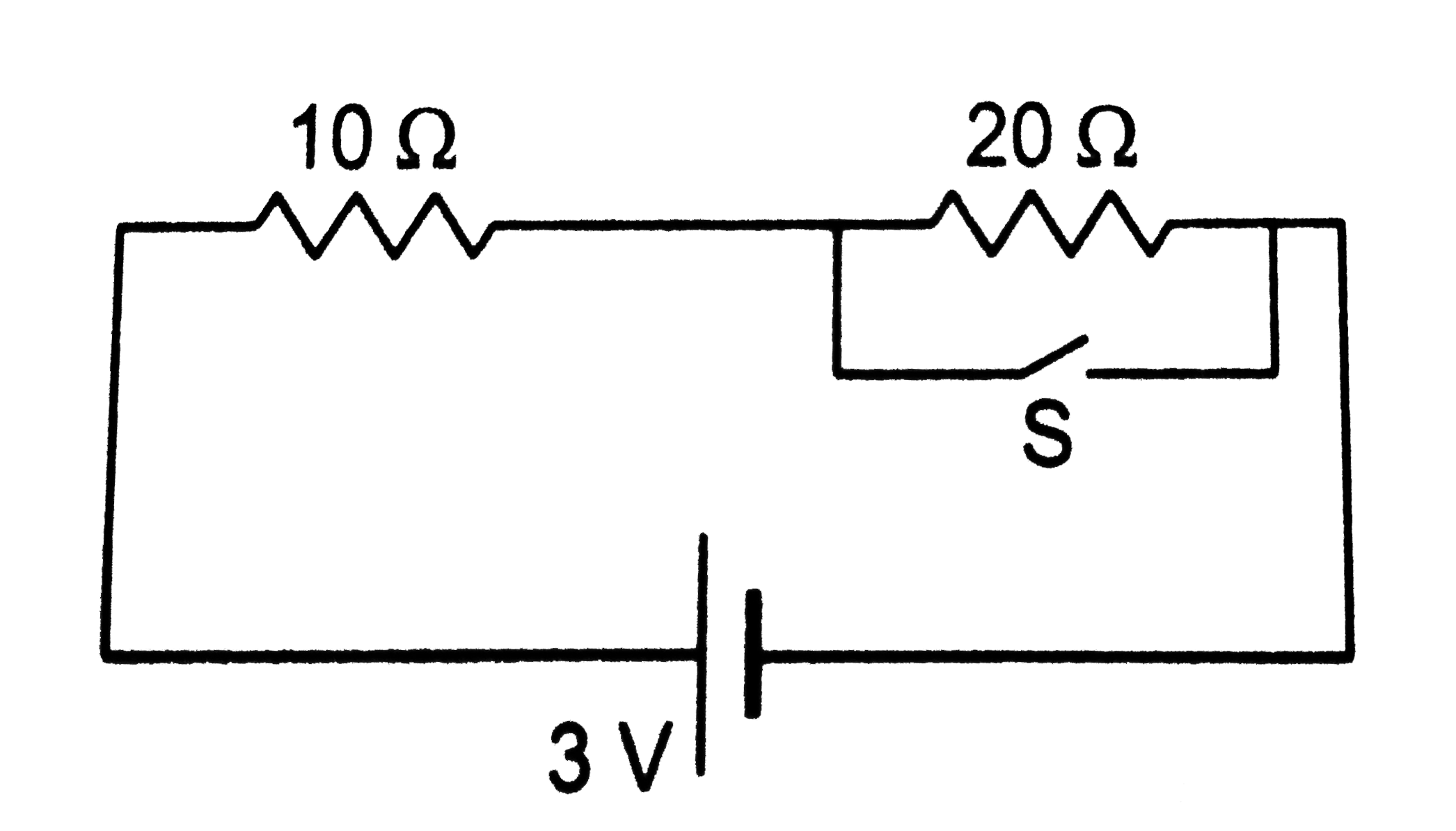 View Solution
In the circuit shown in Fig. 4.41, calculate the current in each resistor and potential difference across each resistor.
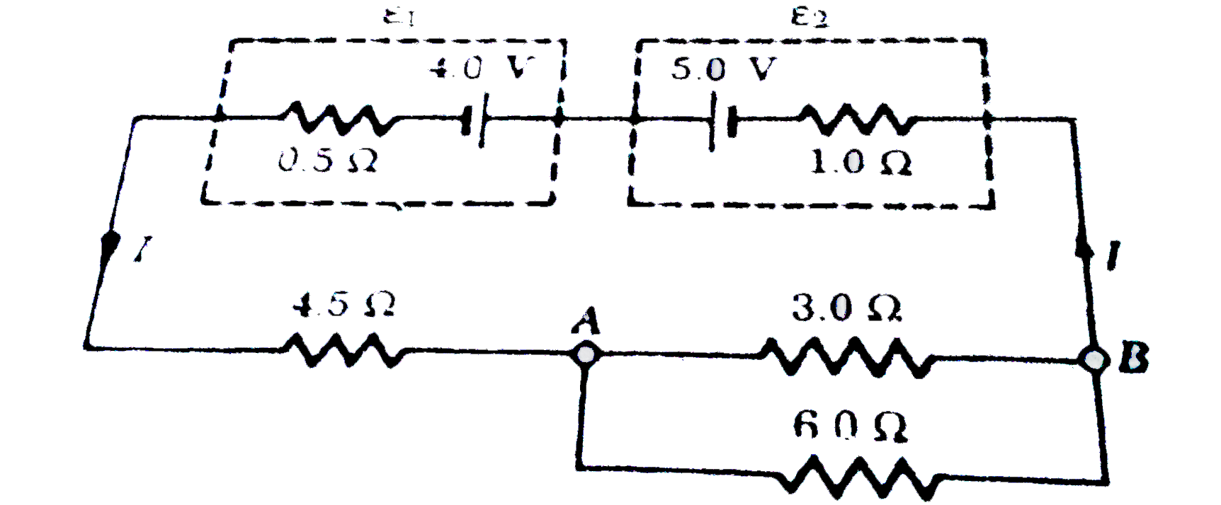 View Solution
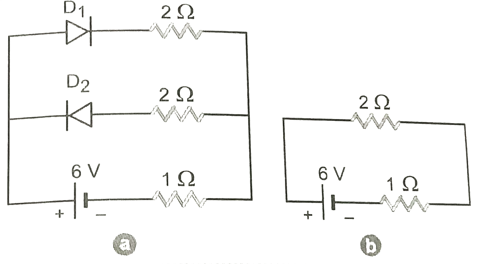
For the circuit shown in Fig., find the current flowing through the 1Ω resistor. Assume that the two diode are ideal diode.
 View Solution


