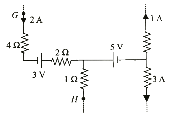
In the part of a circuit shown in fig. 5.266, the potential difference between points G and H will be
A
0 V
B
15 V
C
7 V
D
3 V
Video Solution
Text Solution
The correct Answer is:C
Current through resistance will be 2 A in the upward
direction
|
Topper's Solved these Questions
- ELECTRIC CURRENT AND CIRCUITBOOK - CENGAGE PHYSICSCHAPTER - ELECTRIC CURRENT AND CIRCUITEXERCISE - Multiple Correct
16 Videos
- ELECTRIC CURRENT AND CIRCUITBOOK - CENGAGE PHYSICSCHAPTER - ELECTRIC CURRENT AND CIRCUITEXERCISE - Comprehension
35 Videos
- ELECTRIC CURRENT AND CIRCUITBOOK - CENGAGE PHYSICSCHAPTER - ELECTRIC CURRENT AND CIRCUITEXERCISE - Subjective
29 Videos
- ELECTRIC CURRENT & CIRCUITSBOOK - CENGAGE PHYSICSCHAPTER - ELECTRIC CURRENT & CIRCUITSEXERCISE - Kirchhoff s law and simple circuits
15 Videos
- ELECTRIC FLUX AND GAUSS LAWBOOK - CENGAGE PHYSICSCHAPTER - ELECTRIC FLUX AND GAUSS LAWEXERCISE - MCQ s
38 Videos
Similar Questions
Knowledge Check
In the part of a circuit shown in figure, the potential different
(VG−VH) between points G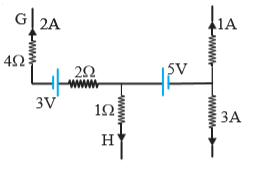 A0VB15VC21VD3V
The potential difference (VA−VB) between the point A and B in the given figure is
 A+6VB+9VC−3VD+3V
The potential difference (VA−VB) between the point A and B as shown in the figure is
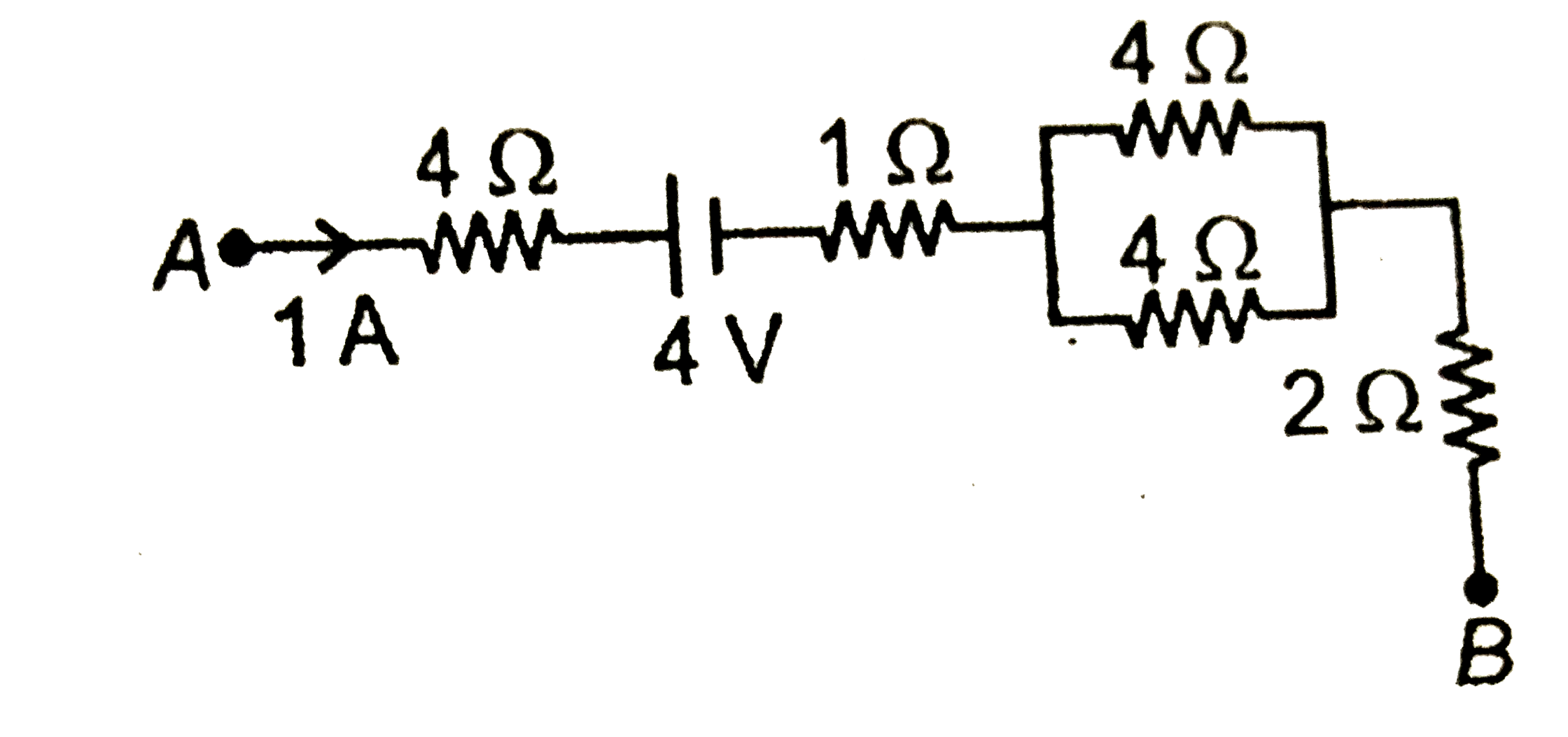 A9VB8VC15VD13V
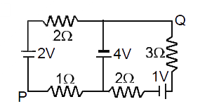
In the circuit shown , what is the potential difference VPQ?
View SolutionThe potential difference (VA−VB) between the point A and B in the given figure is :

View SolutionIn the part of a circuit branch shown in figure-5.304 the potential difference Vab at t=1s is:

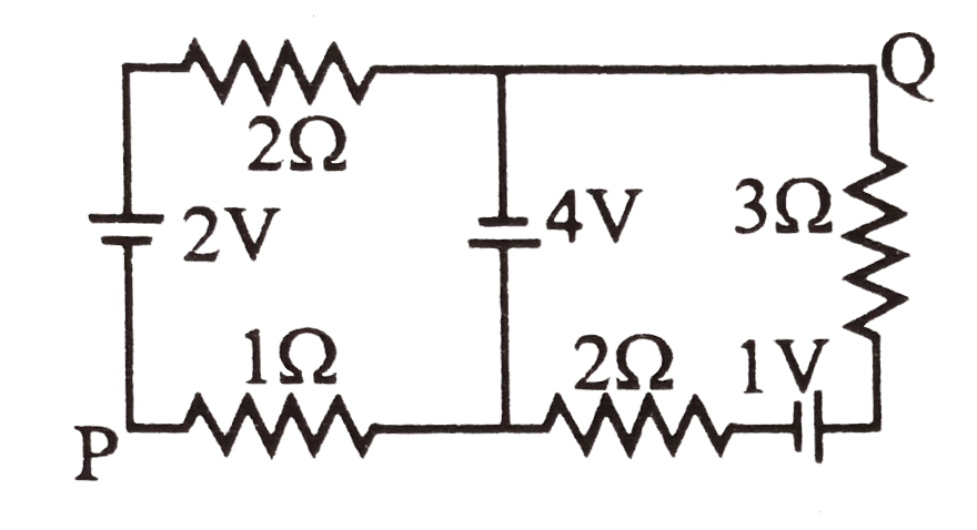
View SolutionIn the circuit shown, what is the potential difference VPQ?
View SolutionThe potential difference (VA−VB) between the point A and B in the given figure is :

View Solution

