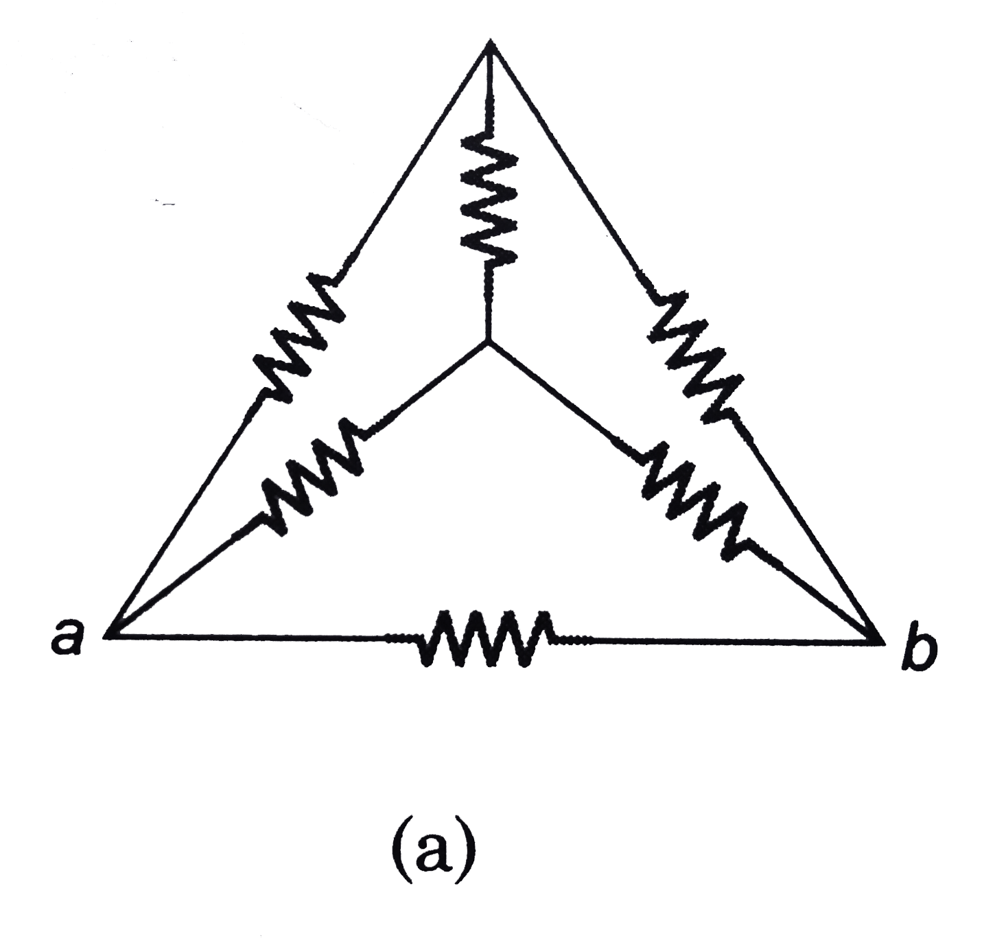
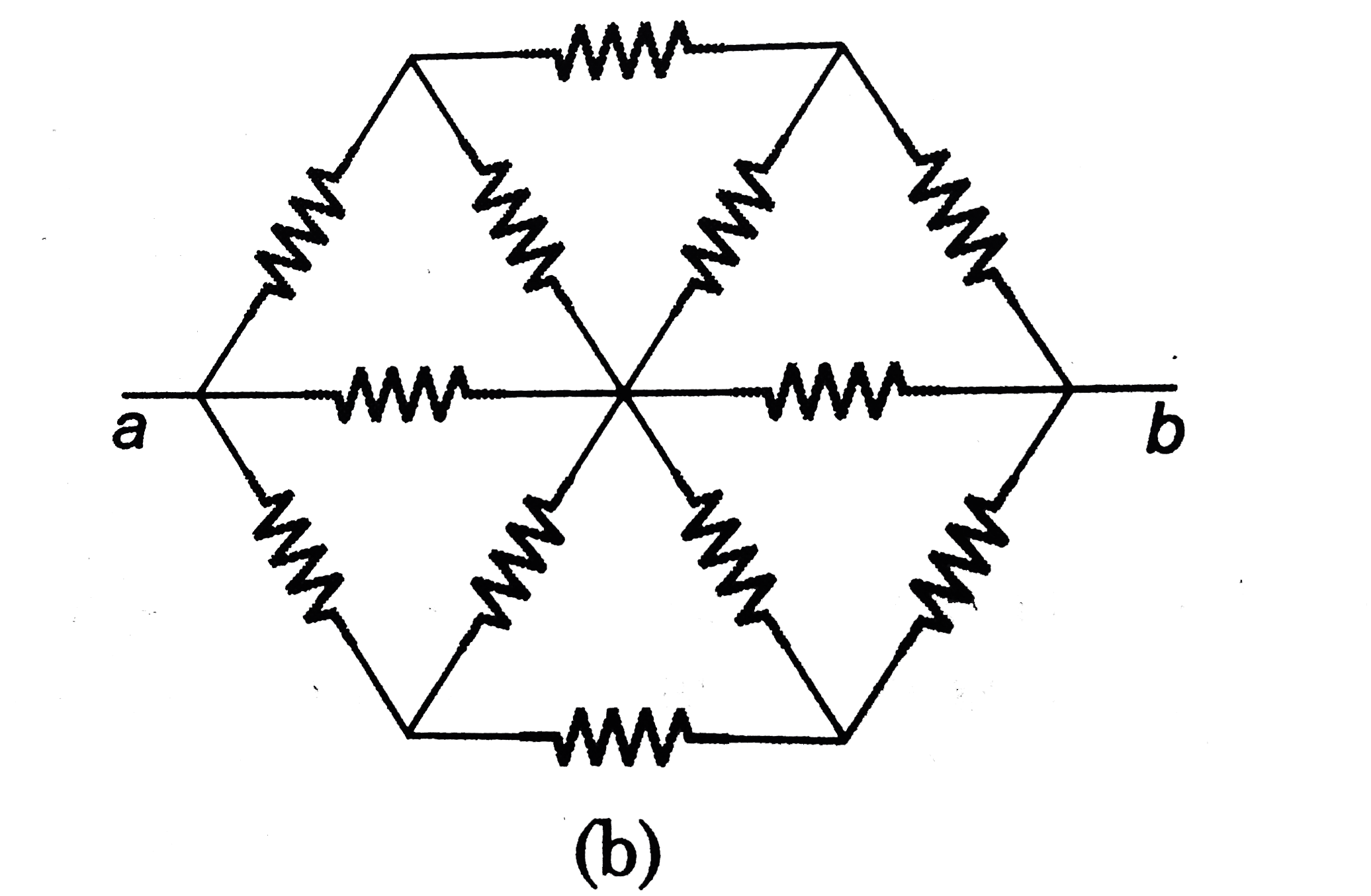
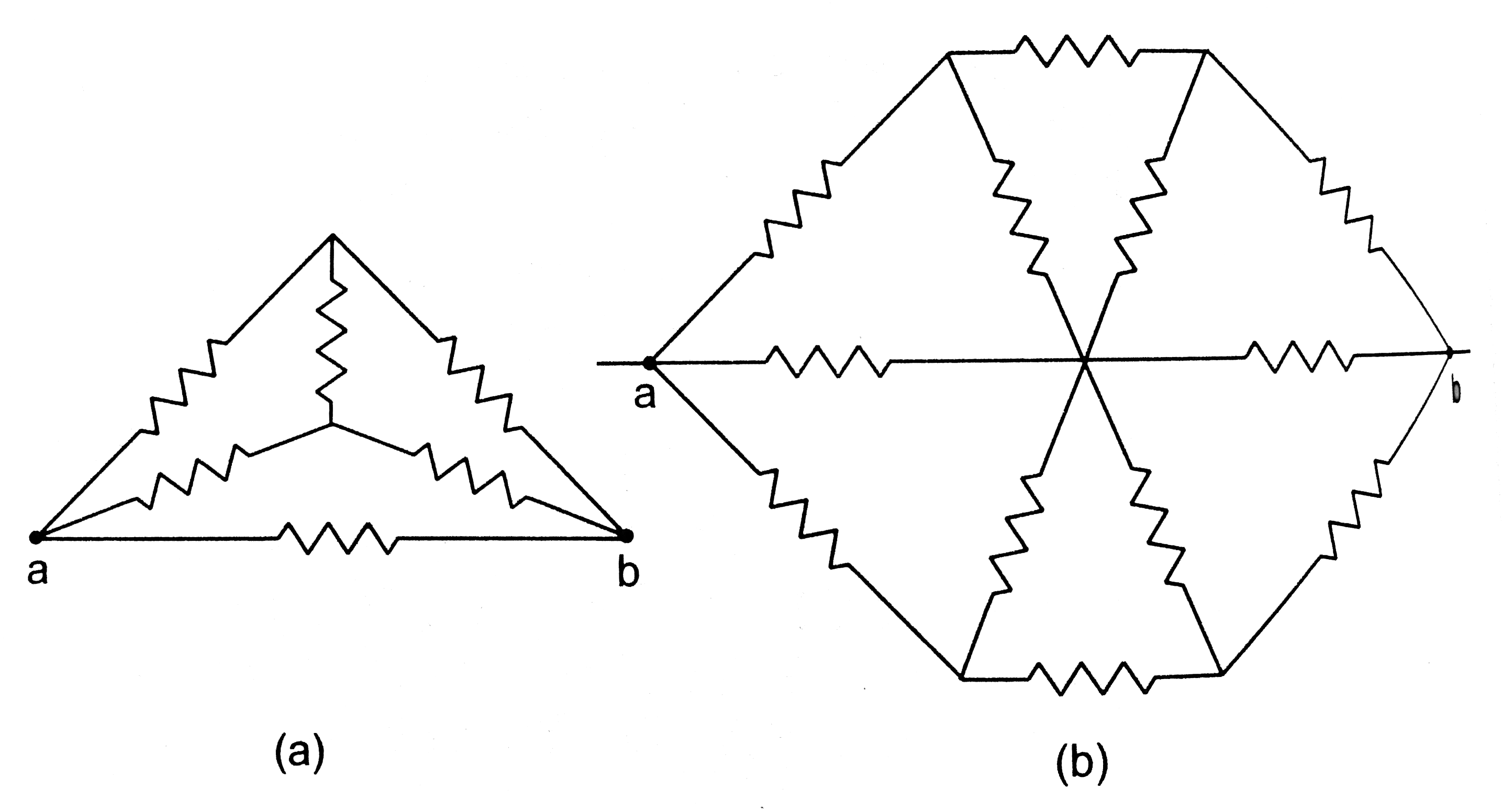
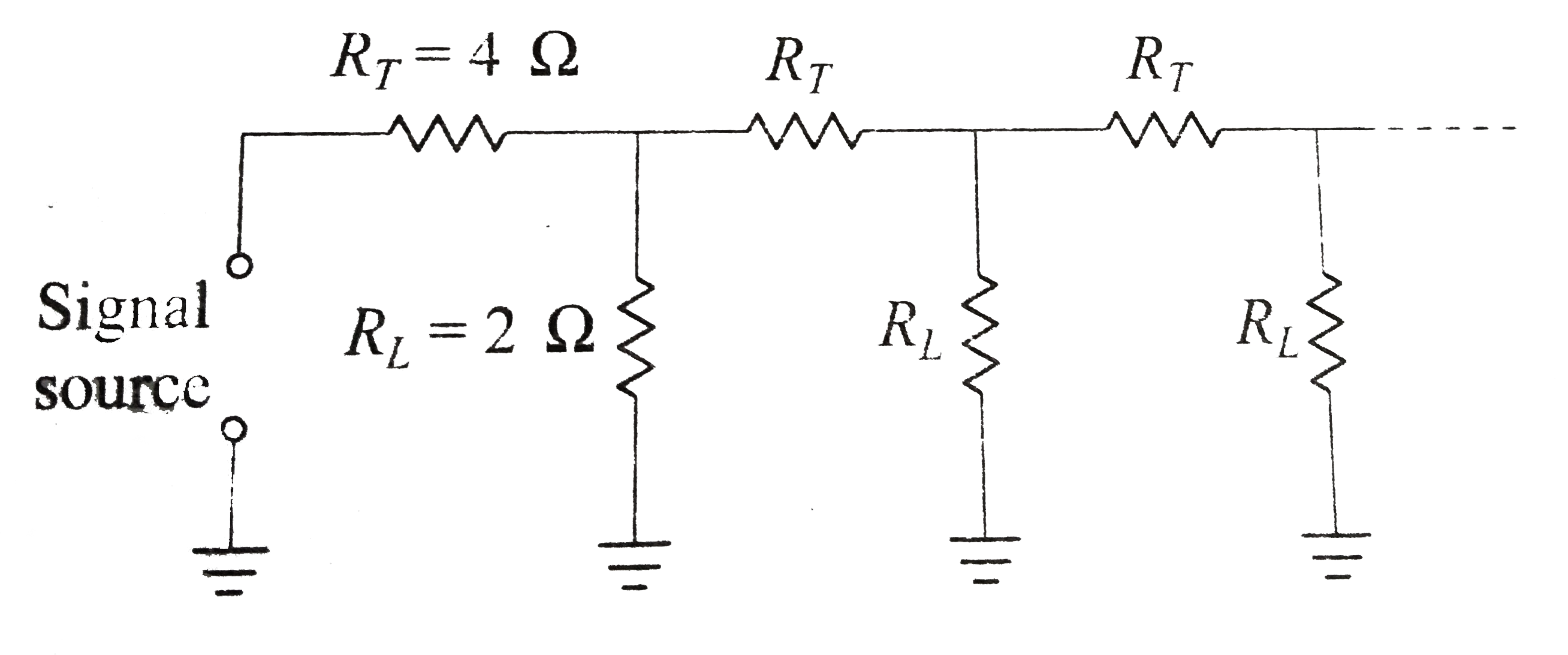
Figure shows a circuit model for the transmission of an electrical signal, such as cable TV, to a large number of subscribers. Each subscriber connects a load resistance RL between the transmission line and the ground. Assume the ground to be at zero potential and to have negligible resistance. The resistance of the transmission line between the connection points of different subscribers is modeled as the constant resistance RT. The equivalent resistance across the signal source is
A
10Ω
B
5Ω
C
√55Ω
D
√65Ω
Video Solution
Text Solution
The correct Answer is:B
b. From the hint, the equivalent resistance of the circuit is
RT+11/RL+1/Req=Req
, <br> <span class=) RT+RLReqRL+Req=Req
RT+RLReqRL+Req=Req
or RTRL+RTReq+RLReq=RLReq+R2eq
or R2eq−RTReq−RTRL=0
or Req=R±√R2T4(1)(−RTRL)2(1)
Only the positive sign is physical.
Req=12(√4RLRT+R2T+RT)
For example, if RT=1ΩandRL=20Ω,Req=5Ω.
|
Updated on:21/07/2023
Similar Questions
Knowledge Check
- Question 1 - Select One
Each resistance of the circuit shown in figure is r. The equivalent resistance between A and B is
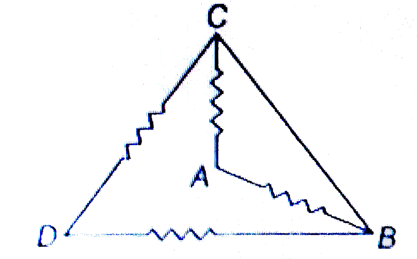 ArBr/4Cr/2D5r/8
 - Question 2 - Select One
Seven resistances are connected The equivalent resistance of this network in between point A and B is
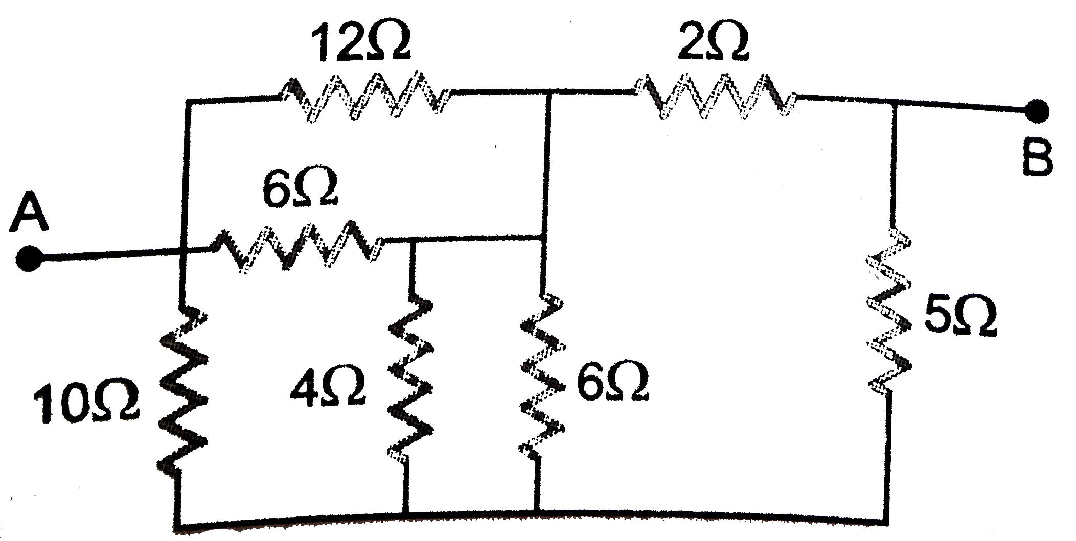 A7.2ΩB3.6ΩC8.6ΩD4.3Ω
 - Question 3 - Select One
The effective resistance of three equal resistances, each of resistance r, connected in parallel, is
A3/rBr/3C3rDr3
Five resistance are connected as shown in the figure. The equivalent resistance between points A and C is
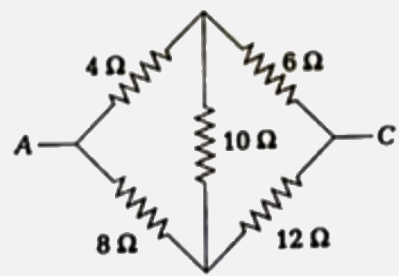 View Solution
Five resistance are connected as shown in the figure . The equivalent resistance between P and Q will be
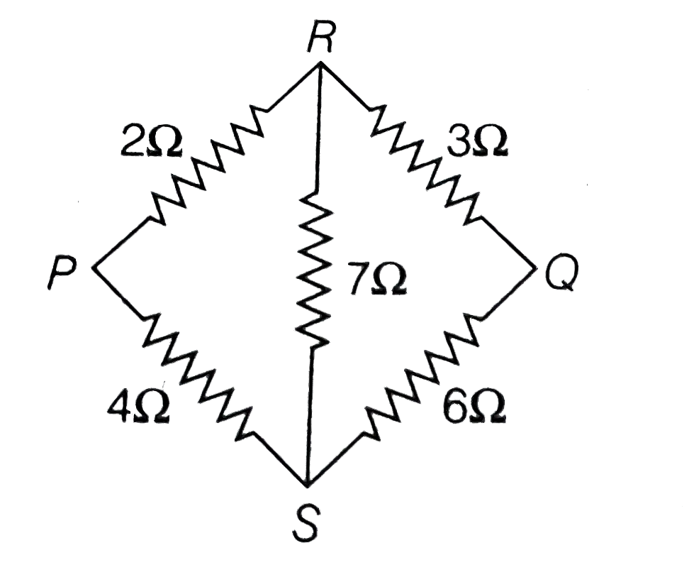 View Solution
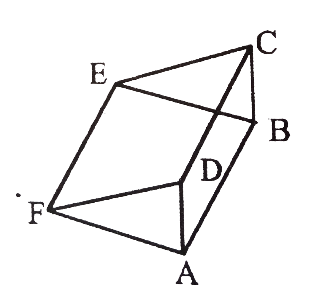
In the circuit shown in figure, all wires have equal resistance r. Find the equivalent resistance between A and B
 View Solution
Find the equivalent resistance of the circuit shown in Fig.4.60 between the points A and B. Each resistor has a resistance r.
 View Solution
A battery of emf epsilon and internal resistance r is connected across a load resistance RL . The plot between output power and load resistance is shown in the figure
_PHY_E05_112_Q01.png) The value of emf epsilon and internal resistance r respectively will be View Solution
The value of emf epsilon and internal resistance r respectively will be View Solution

