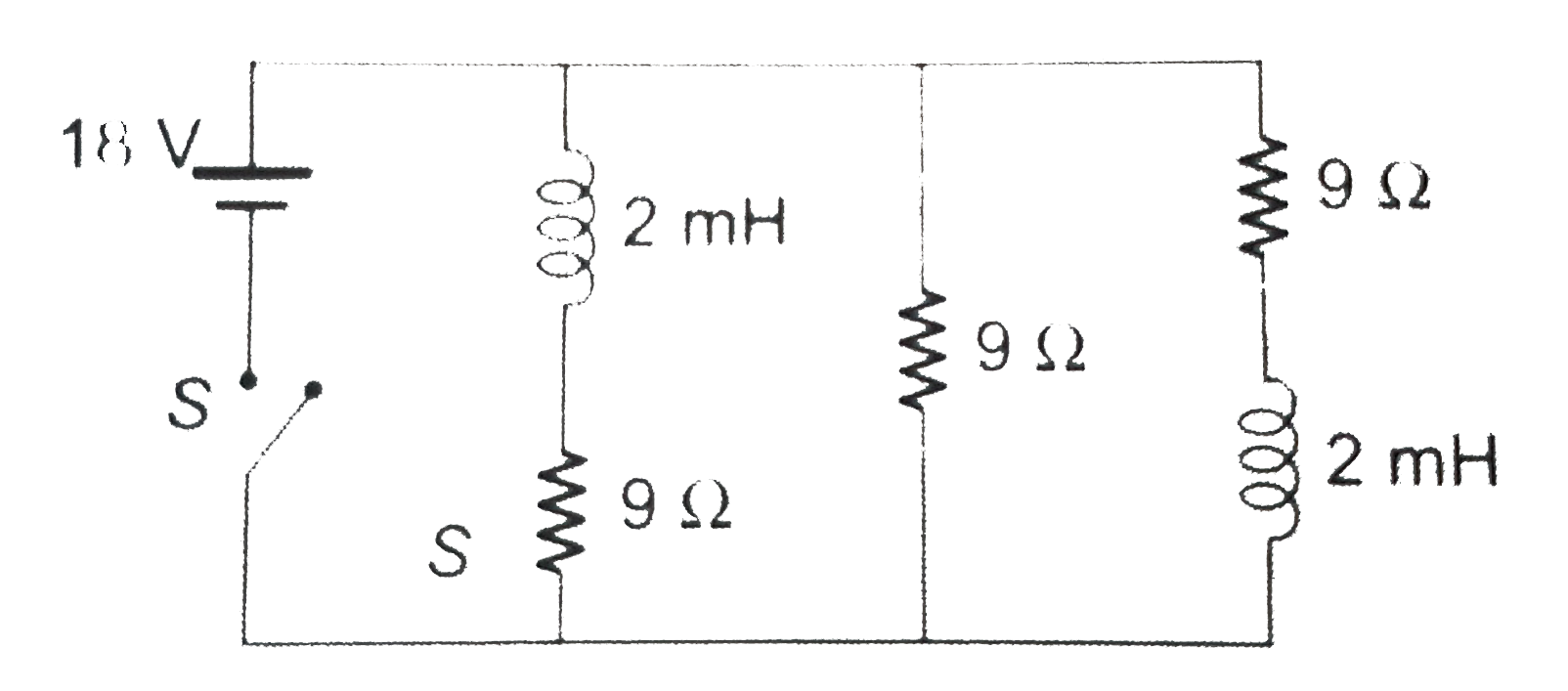
A conducting ring is placed near a solenoid as shown in Fig.3.21. Find the direction of the induced current in the ring.
(a) At the instant the switch in the circuit containing the solenoid is closed.
(b) After the switch has been closed for a long time.
(c) At the instant the switch is opened.
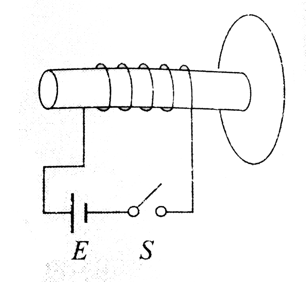
(a) As the switch is closed, the situation changes from one in which no magnetic flux passes through the ring to the one in which flux passes through the ring in the direction shown. The induced current flows in the aniclockwise sense as seen from the side on which the solenoid lies.
(b) When the switch has been closed for a long time, no change in the magnetic flux through the loop occurs, hence, no current is induced in the loop.
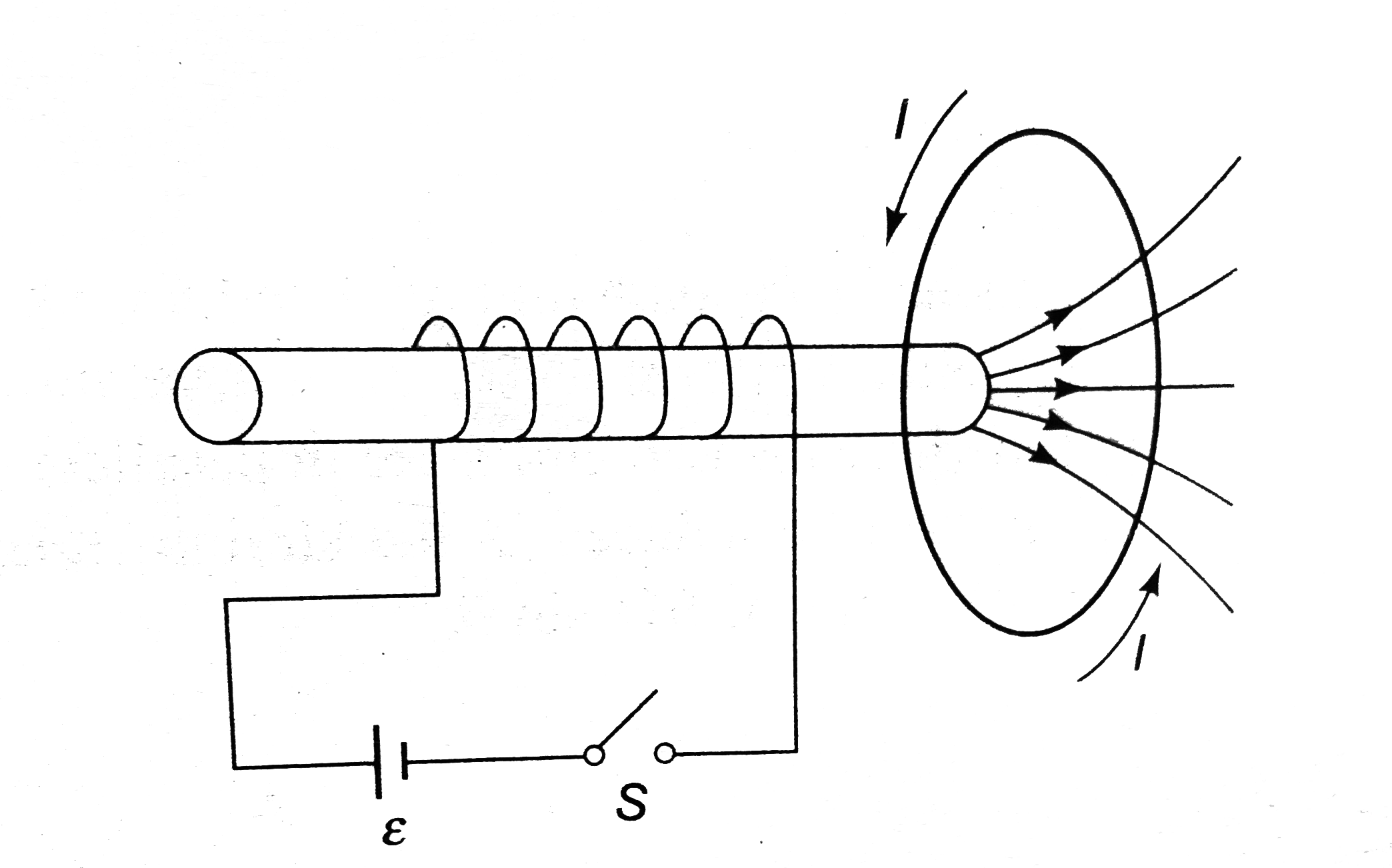
( c) When the switch is opened, flux in the direction shown above. Hence current will be opposite to teh diretion of situation (a), i.e., in clockwise direction.
Topper's Solved these Questions
- ELECTROMAGNETIC INDUCTIONBOOK - CENGAGE PHYSICSCHAPTER - ELECTROMAGNETIC INDUCTIONEXERCISE - Exercise 3.2
27 Videos
- ELECTROMAGNETIC INDUCTIONBOOK - CENGAGE PHYSICSCHAPTER - ELECTROMAGNETIC INDUCTIONEXERCISE - Exercises Subjective
13 Videos
- ELECTROMAGNETIC INDUCTIONBOOK - CENGAGE PHYSICSCHAPTER - ELECTROMAGNETIC INDUCTIONEXERCISE - Solved Example
5 Videos
- ELECTROMAGENTIC INDUCTIONBOOK - CENGAGE PHYSICSCHAPTER - ELECTROMAGENTIC INDUCTIONEXERCISE - QUESTION BANK
40 Videos
- ELECTRON,PHONTS,PHOTOELECTRIC EFFECT & X-RAYSBOOK - CENGAGE PHYSICSCHAPTER - ELECTRON,PHONTS,PHOTOELECTRIC EFFECT & X-RAYSEXERCISE - dpp 3.3
15 Videos
Similar Questions
Knowledge Check
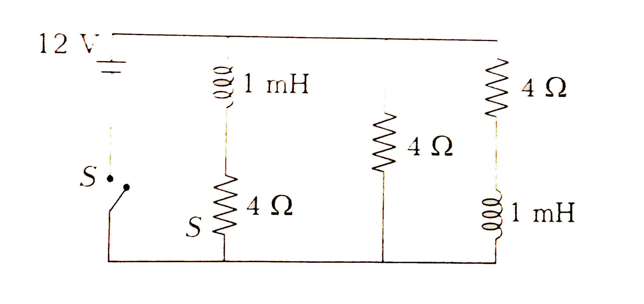
In Fig. switch S is closed for a long time. At t=0, if it is opened, then
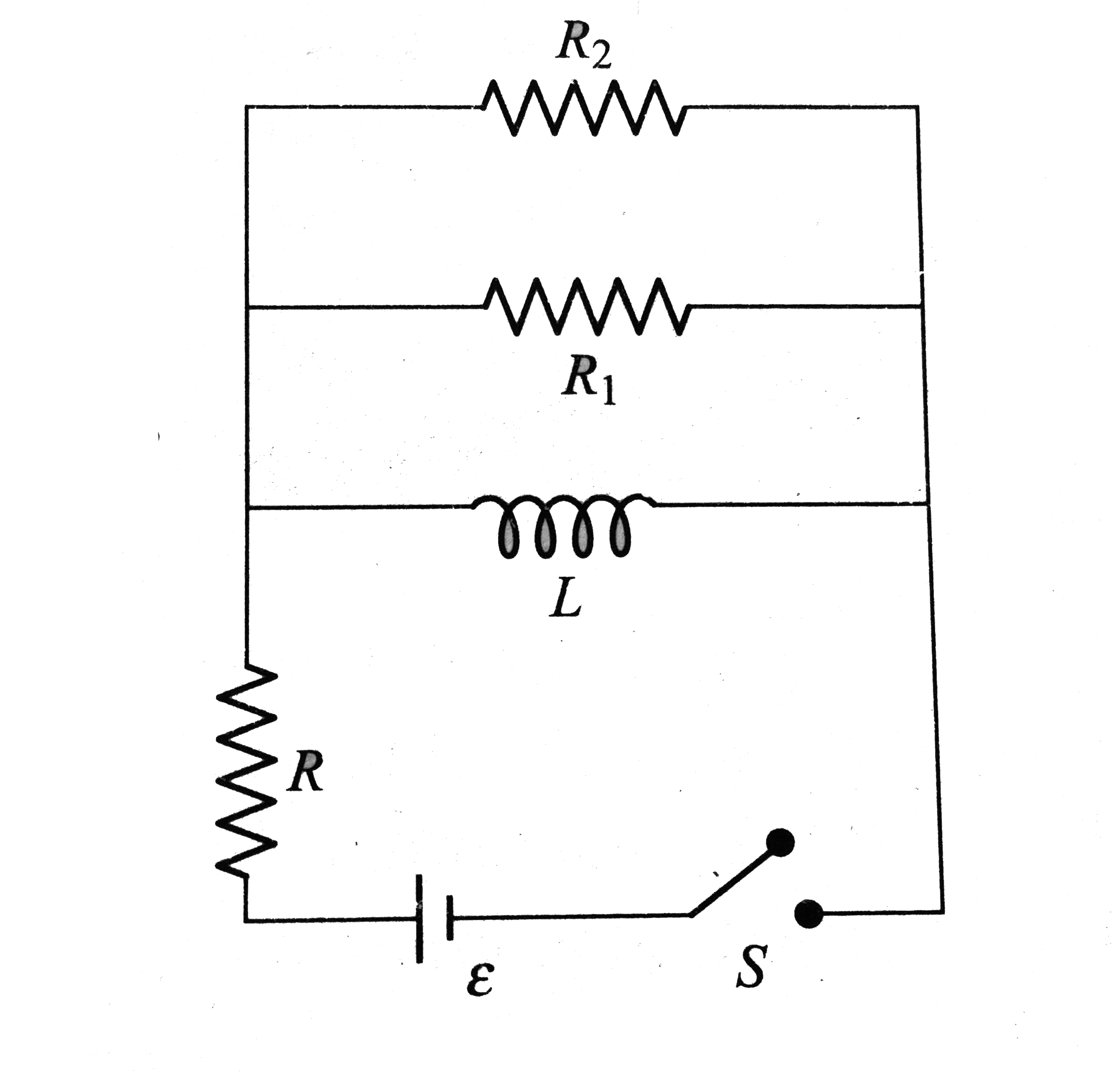 Atotal heat produced in resistor R after opening the switch is 12LεR2Btotal heat produced in resistor R1 after opening the switch is 12Lε2R2(R1R1+R2)Cheat produced in resistor R1 after opening the switch is 12R2Lε2(R1+R2)R2Dno heat will be produced in R1
In the circuit as shown in figure the switch is closed at t=0.
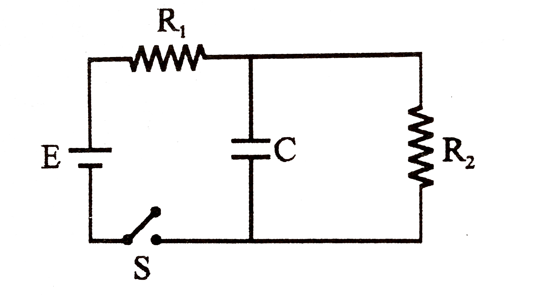
At the instant of closing the switchAthe battery delivers maximum currentBno current flows through CCvoltage drop across R2 is zeroDthe current through the battery decreases with time finally becomes zeroIn the circuit shown in the figure, if switches S1 and S2 have been closed for a long time, then charge on the capacitor.
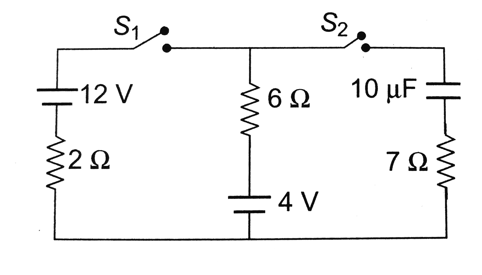 Ais 100μCBincreases to 200μC if one third of the gap of the capacitor's plates is filled with a dielectric (K=2) of same areaCboth (a) and (b) aboveDcharge on the capacitor remains unchanged if one third of the gap of the capacitor's plates is filled with a dielectric (K=2) of same area.
Find the current through the battery
(i) just after the switch is closed.
(ii) long after the switch has been closed.
View SolutionA small, circular ring is inside a larger loop that is connected to a battery and a switch as shown in Fig. 3.25. Use Lenz's law to find the direction of the current induced in the small ring
(a) just after switch S is closed,
(b) after Shas been closed for a long time,
( c) just after S has been reopened after being closed for a long time. ltbr>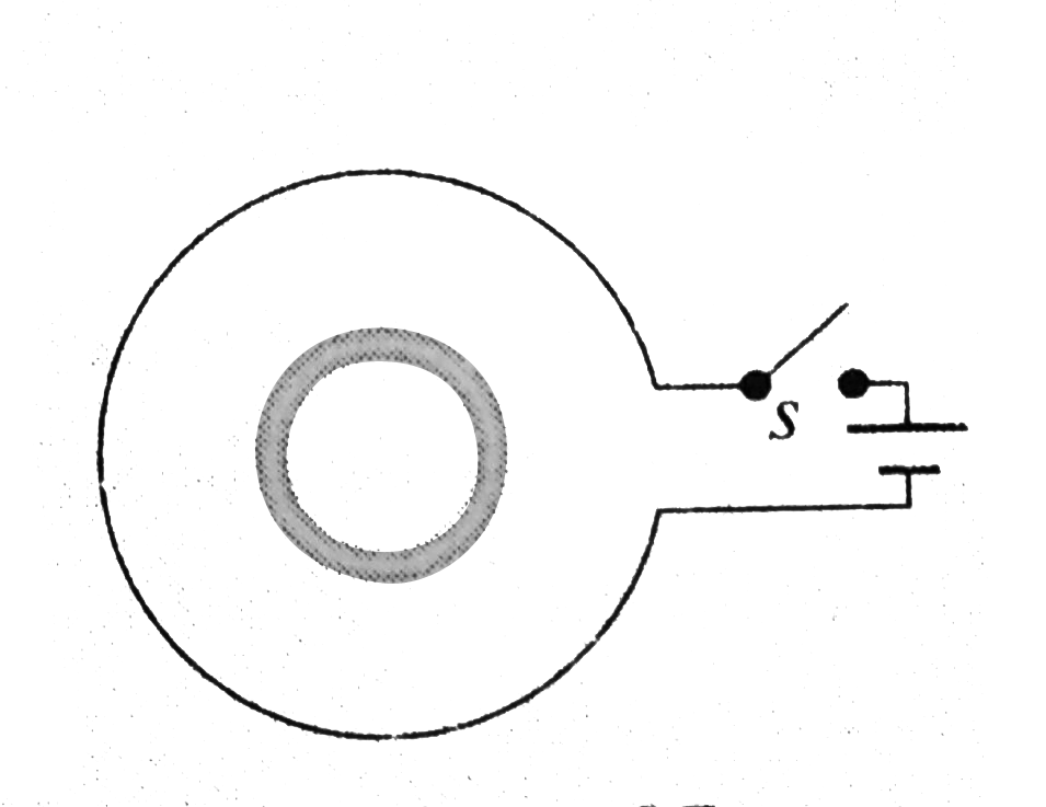
View SolutionDetermine the current through the battery in the circuit shown in figure.
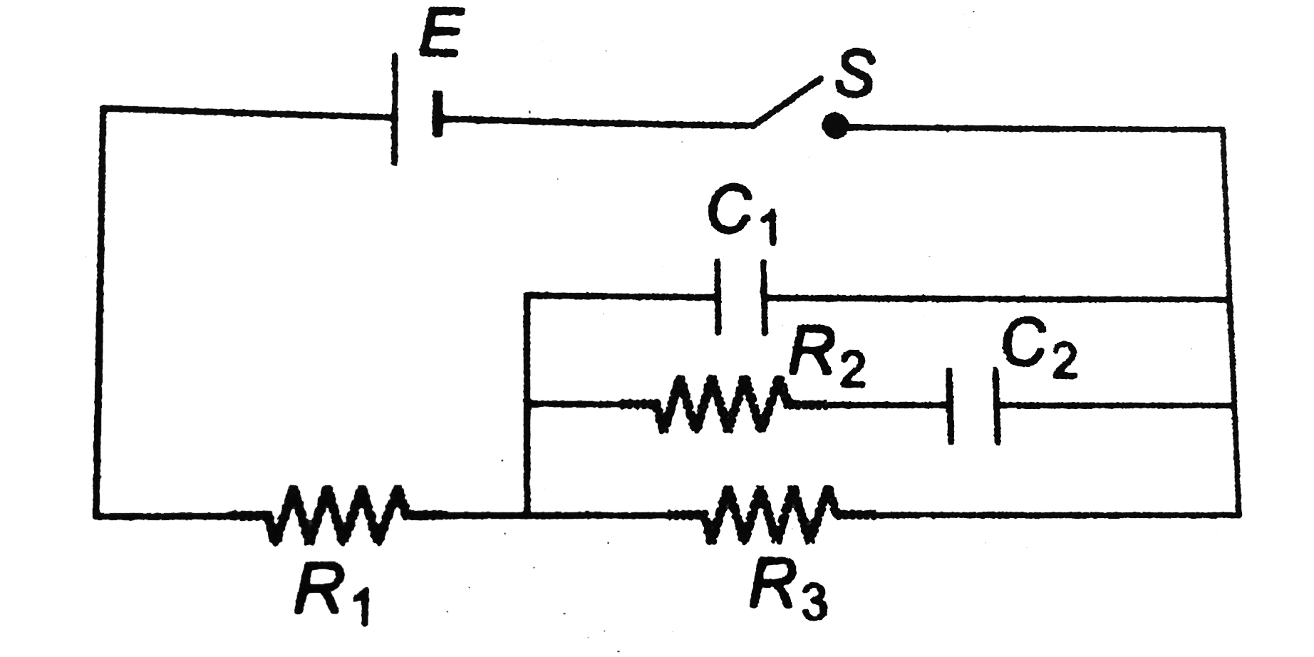
(a) immediately after the switch S is closed
(b) after a long time.
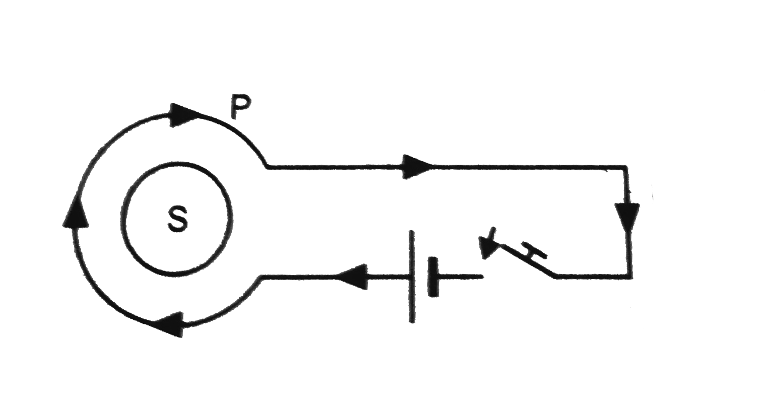
View SolutionIn fig. P and S are two coils. What shall be the direction of induced momentary current in S immediately after the switch is closed, (ii) if the switch is opened, after it the been closed for some time,
View SolutionFind out current in the circuit and charge on capacitor which is initially uncharged in the following situations.
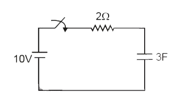
(a) Just after the switch is closed
(b) After a long time when switch was closed.
View Solution


