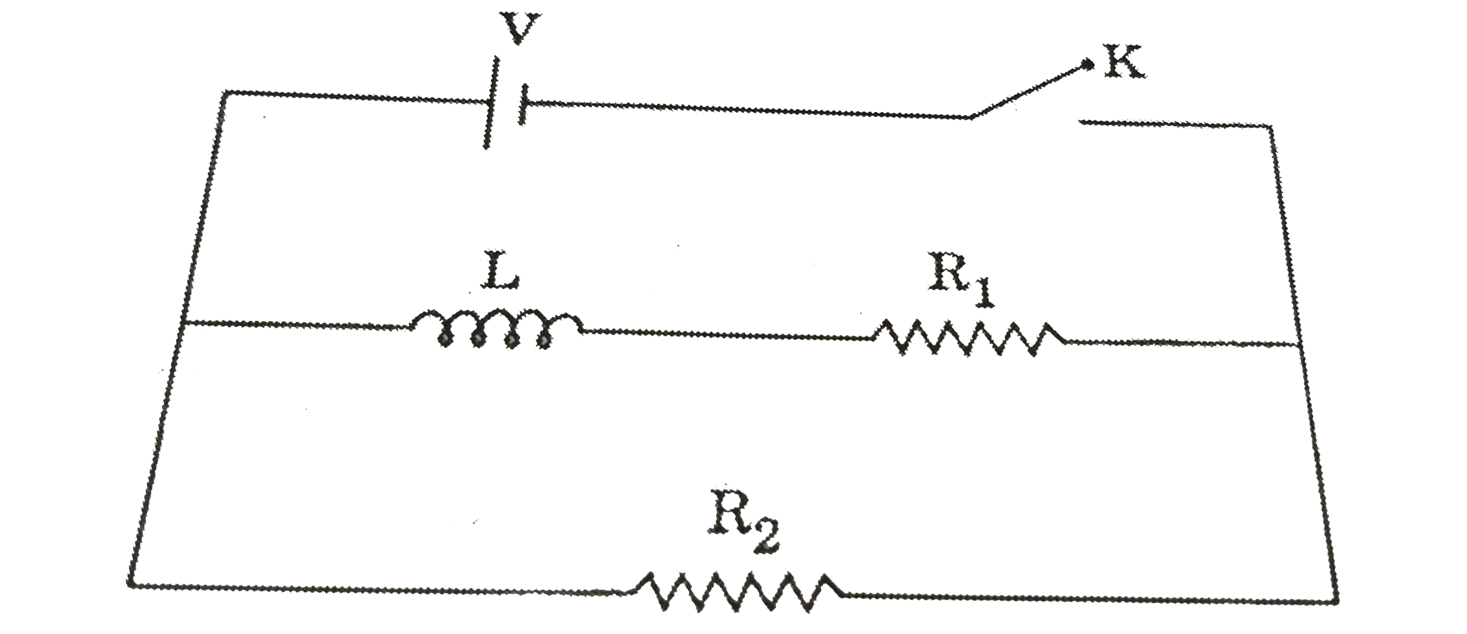
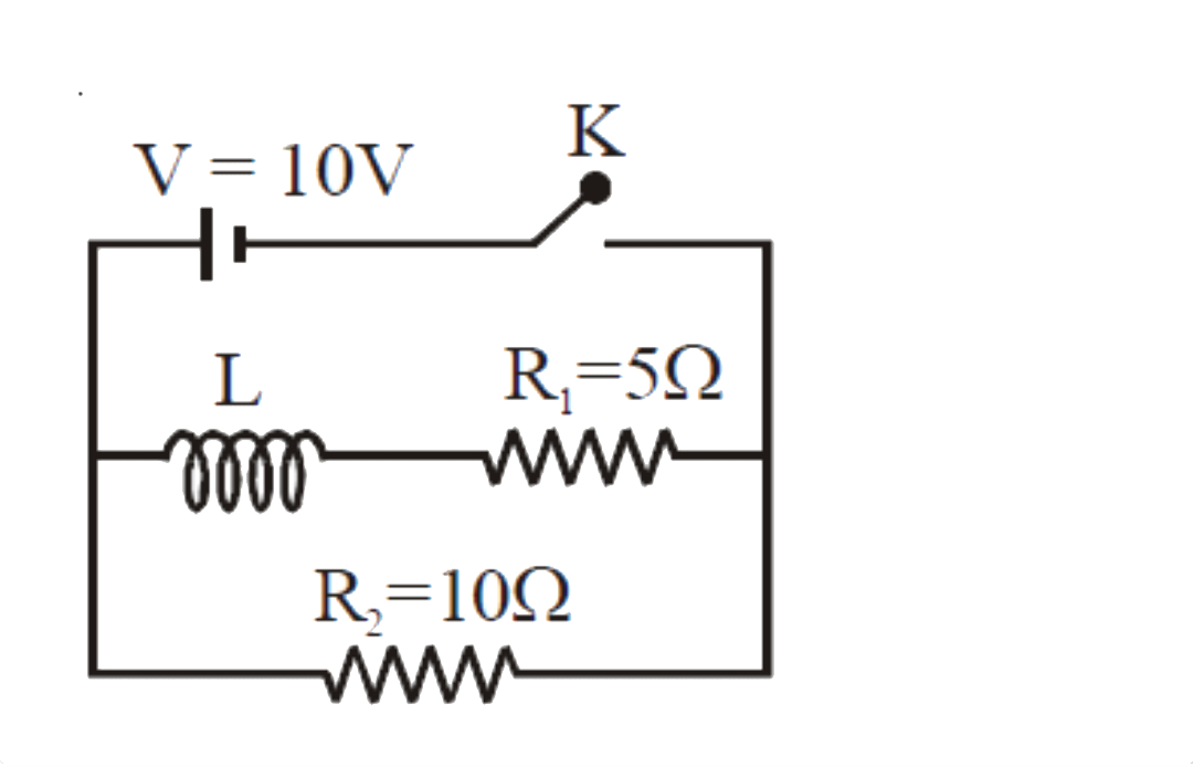
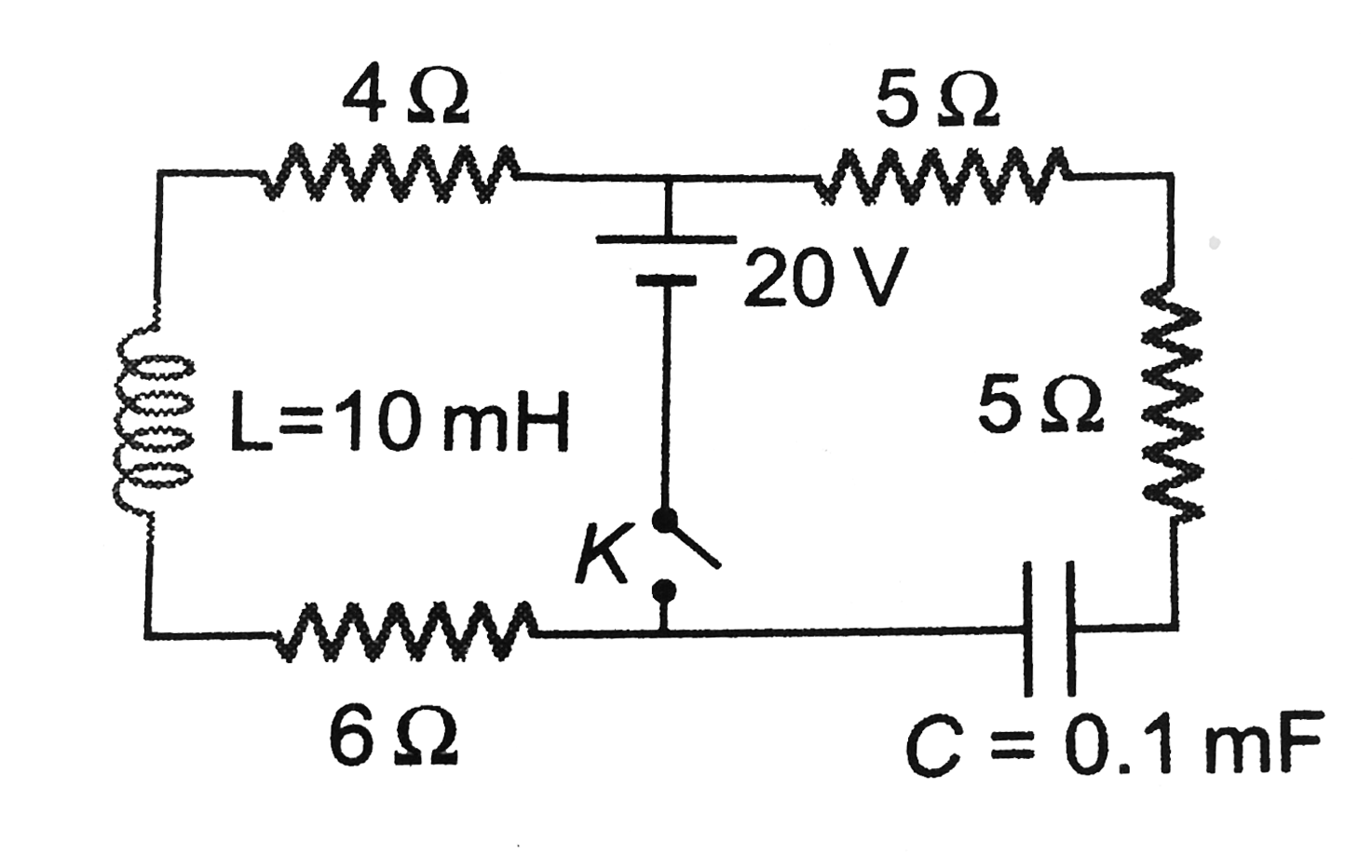
In the circuit shows in Fig. kay K is closed at t=0, the current through the key at the instant t=10−3In2s is
A
2A
B
3.5A
C
2.5A
D
0
Video Solution
Text Solution
The correct Answer is:C
Current in branches containing L and R will flow independently
I1=2010(1−e−t5×10−4)=32=1.5A
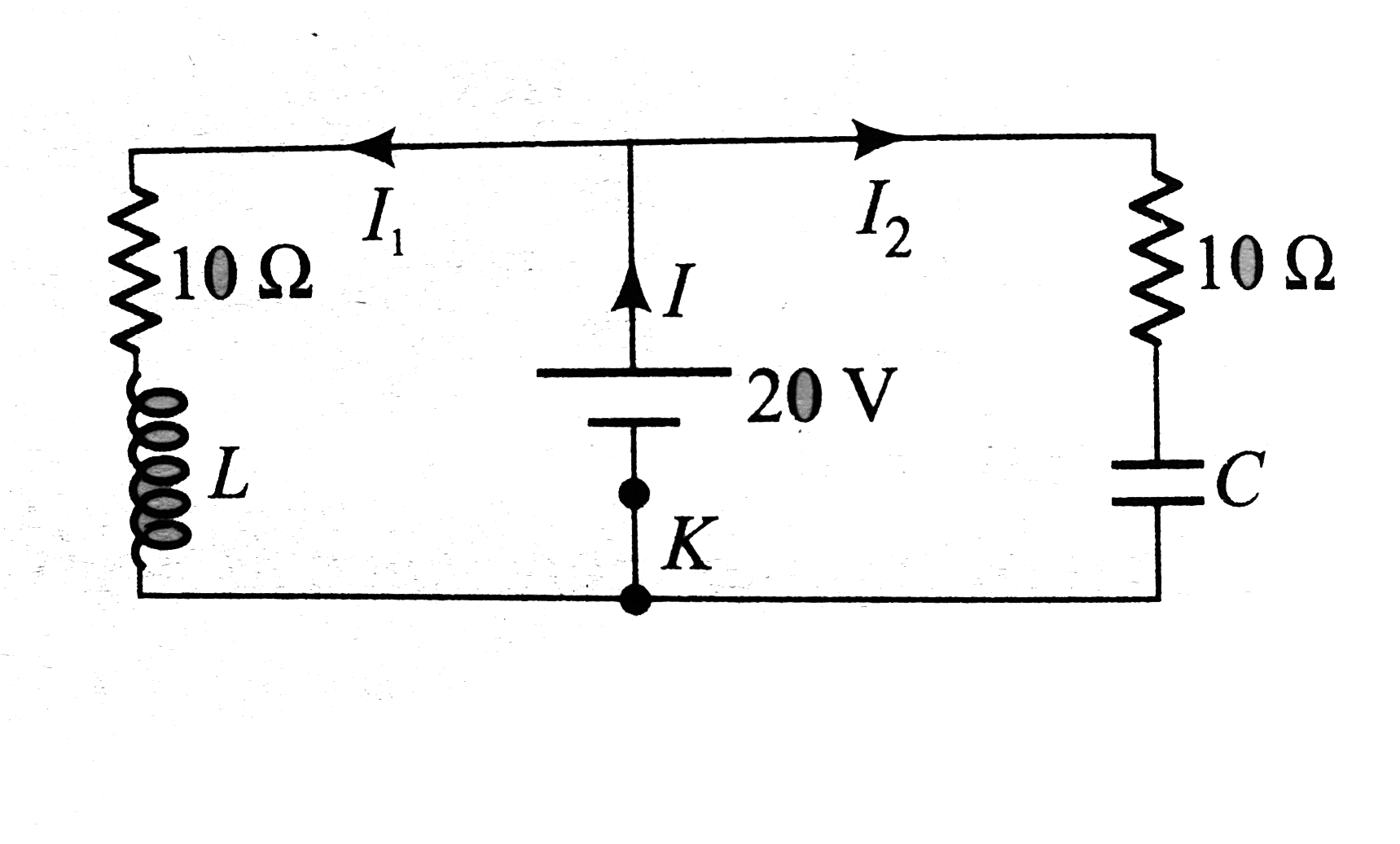
I2=2010e−t10−3=1.0A
I=I1+I2=2.5A
|
Updated on:21/07/2023
Topper's Solved these Questions
- BOOK - CENGAGE PHYSICSCHAPTER - INDUCTANCEEXERCISE - Exercises (multiple Correct )7videos
INDUCTANCE
- BOOK - CENGAGE PHYSICSCHAPTER - INDUCTANCEEXERCISE - Exercises (assertion-reasoning)2videos
INDUCTANCE
- BOOK - CENGAGE PHYSICSCHAPTER - INDUCTANCEEXERCISE - Exercises (subjective)7videos
INDUCTANCE
- BOOK - CENGAGE PHYSICSCHAPTER - HEATING EFFECT OF CURRENTEXERCISE - Thermal Power in Resistance Connected in Circuit28videos
HEATING EFFECT OF CURRENT
- BOOK - CENGAGE PHYSICSCHAPTER - KINETIC THEORYEXERCISE - Question Bank31videos
KINETIC THEORY
Similar Questions
Knowledge Check
- Question 1 - Select One
In the circuit shown the key (K) is closed at t=0, the current through the key at the instant t=10−3ln,2 is
 A2AB8AC4ADzero
 - Question 2 - Select One or More
In the circuit shows in Fig the switch is closed at t=0.
 AAt t=0,I1=I2=0BAt any time t,I0I2=L2L1CAt any time t, I1+I2=εRDAt t=∞,I1 and I2 are independent of L1 and L2
 - Question 3 - Select One or More
In the circuit shown key is closed at t=0 with capacitor initially uncharged.
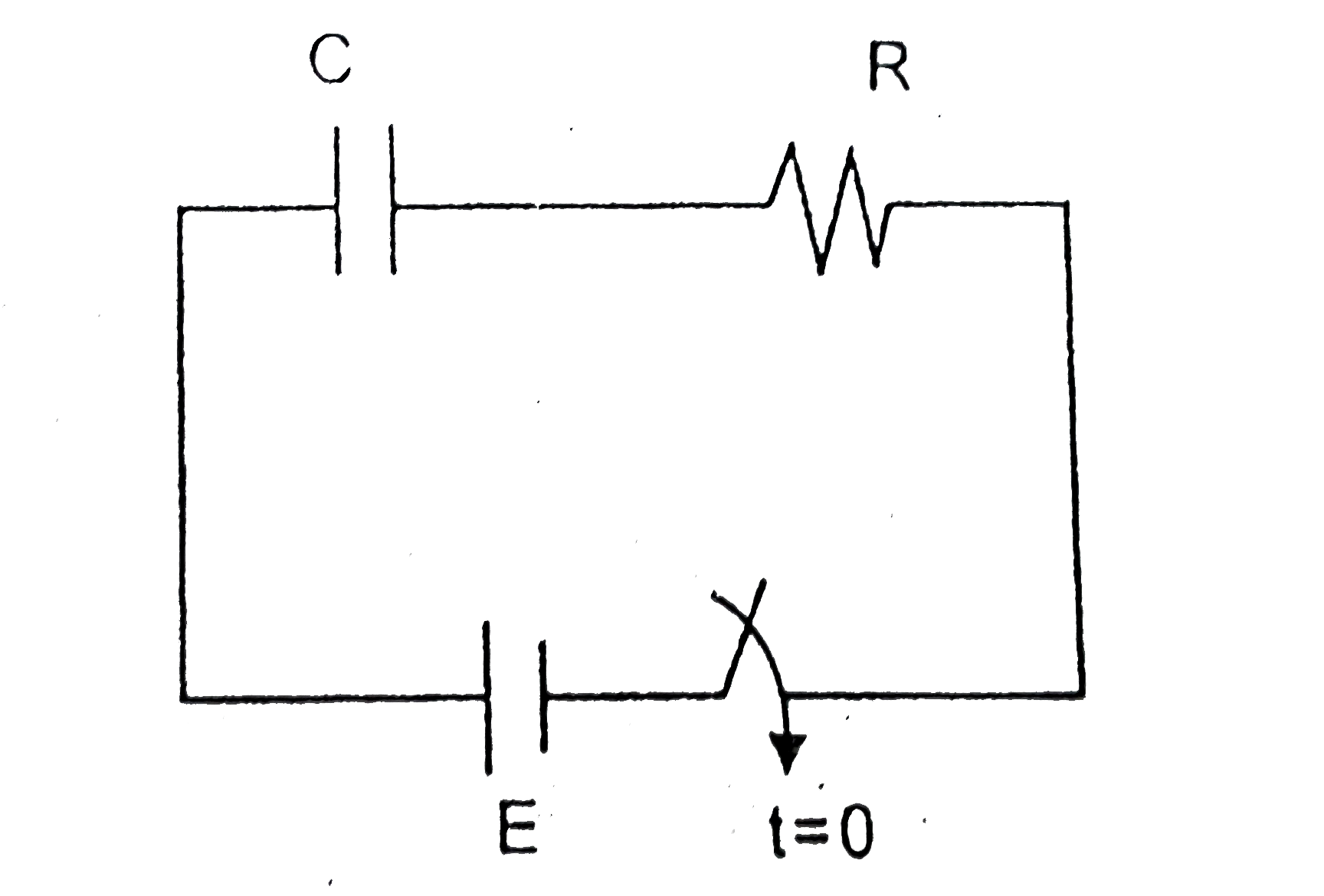 ARate of increase of capacitors energy, just after the switch is closed is E2RBMaximum power supplied by the cell is E2RCAt t=RCIn2, capacitor is charged up to half of the energy stored by it in steady stateDAt t=RCIn2, potential difference across capacitor is same that across resistor.
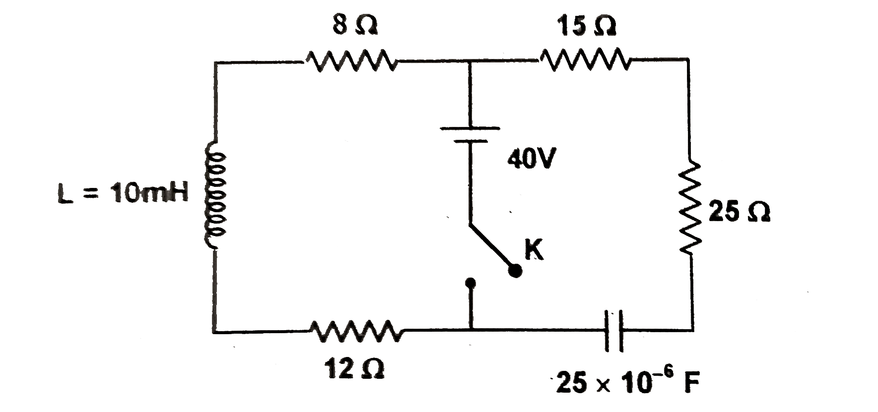
In th circuit the key (K) is closed at t=0. Find the current in ampere through the key (K) at the instant t=102ln2 sec.
 View Solution
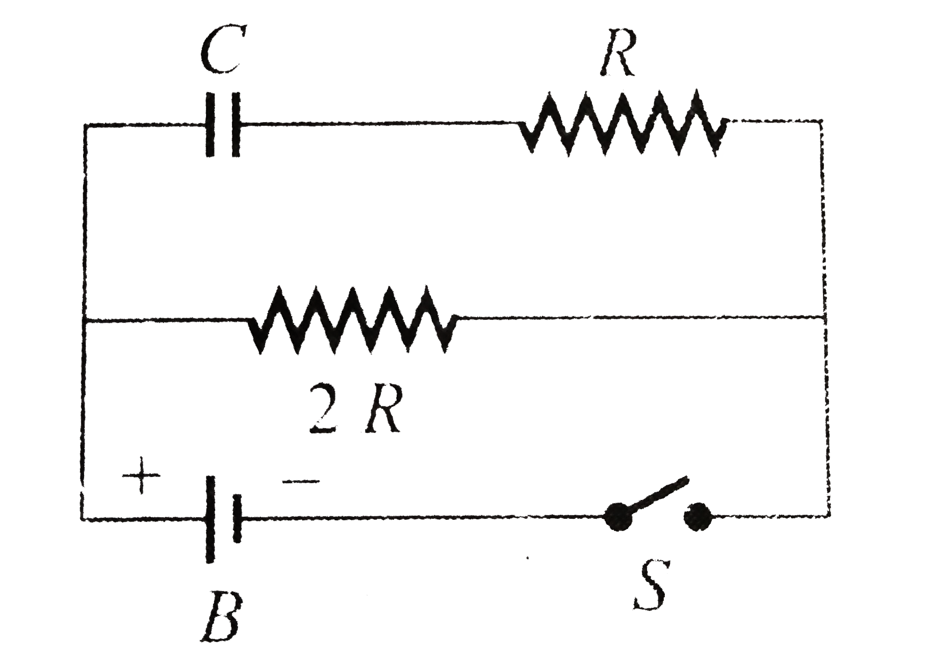
In the circuit shown in fig, if the switch S is closed at t=0 , the capacitor charges with a time constant
 View Solution
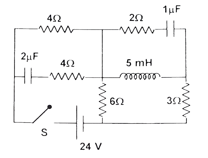
In the circuit shown, the switch 'S' is closed at t=0. Then the current through the battery steady state reached is
 View Solution
In the circuit shown in figure switch S is closed at time t=0
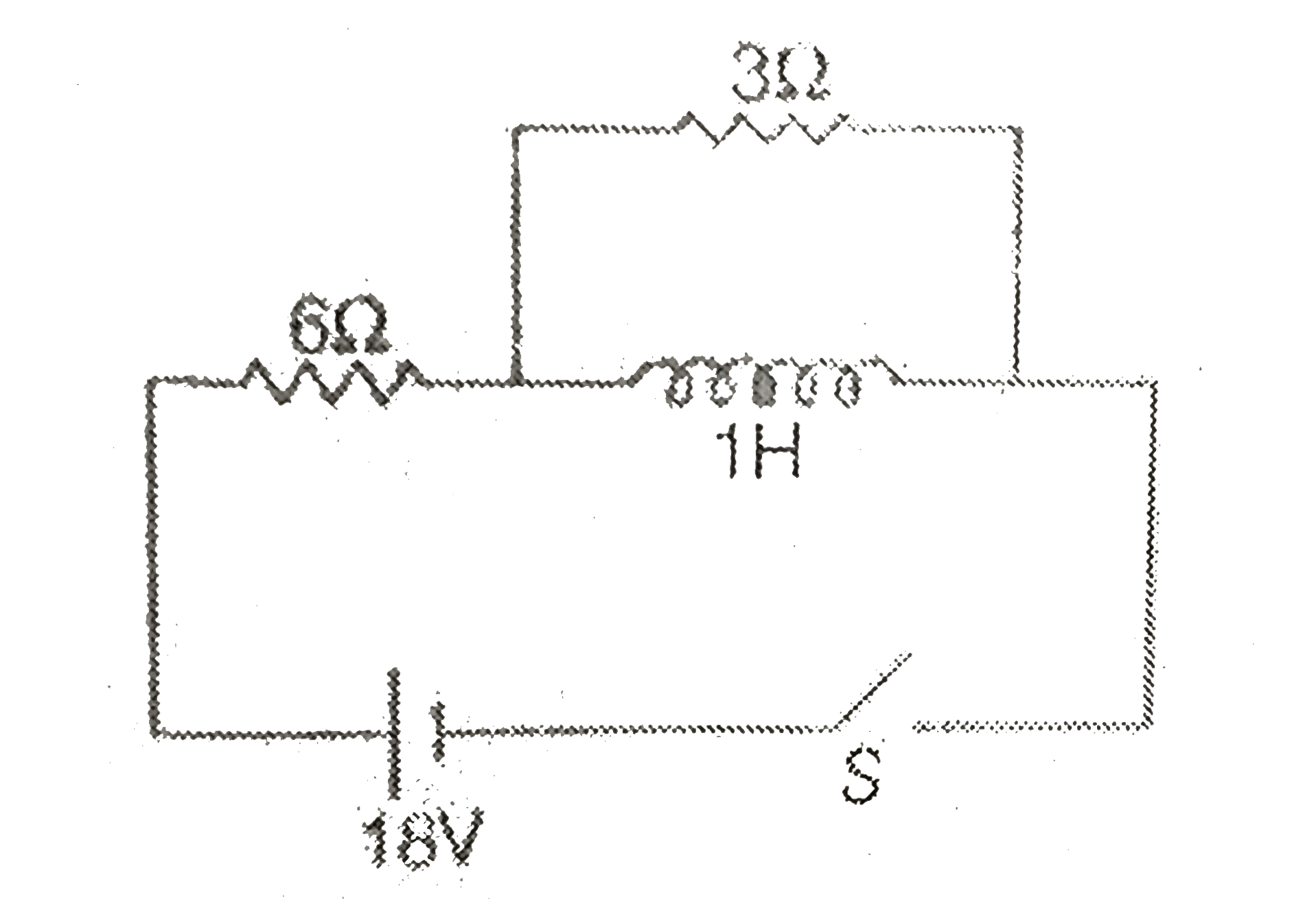
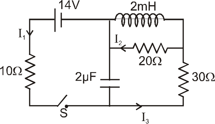
Current I from the battery at time t is given byView SolutionIn the circuit shown, the switch is closed at t=0, the currents I1,I2 and I3 are
 View Solution


