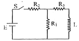
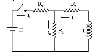
In the circuit shows in Fig , , , , and . The currents flowing through ,and are , and , respectively.
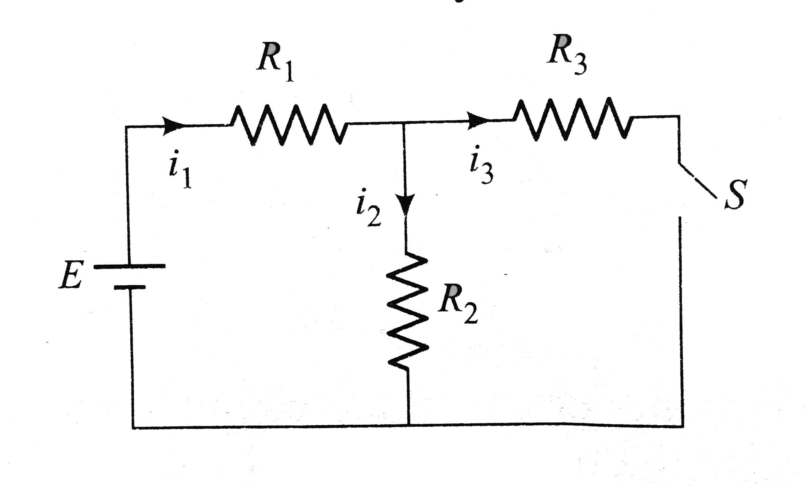
After the circuit reaches the steady state,
, ,
, ,
, ,
, ,
The correct Answer is:A
At , circuit can be considered as follows:
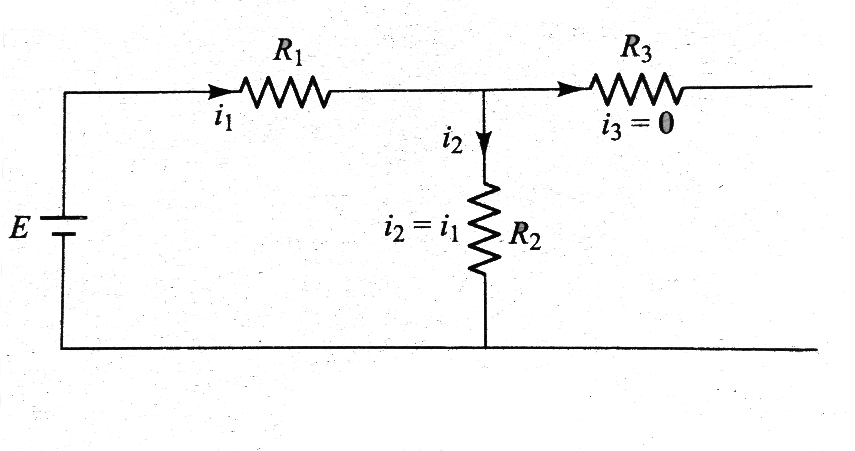
After a long, circuit can be considered a sfollow:
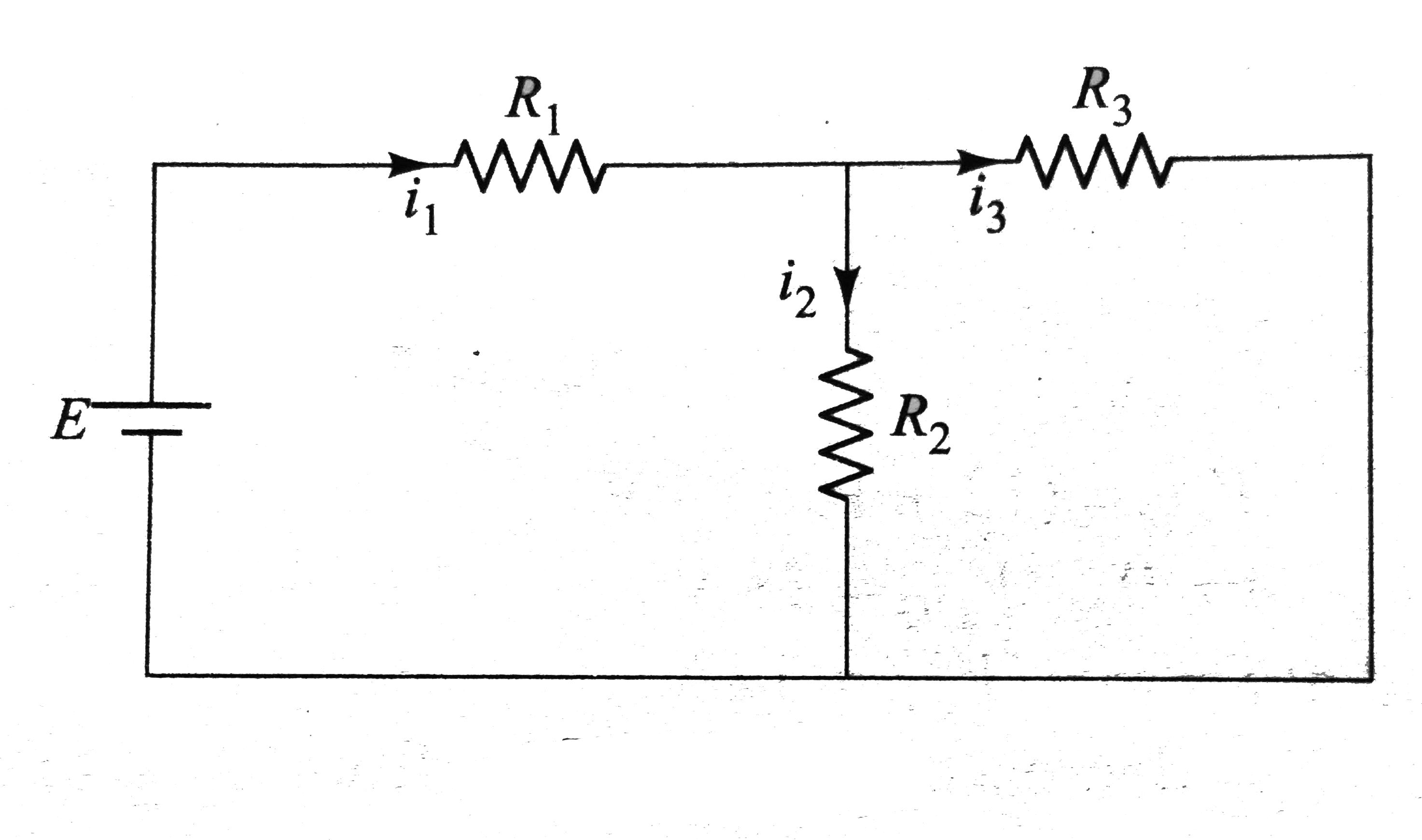
Immediately after closing , . Because induced e.m.f.
.
Topper's Solved these Questions
- INDUCTANCEBOOK - CENGAGE PHYSICSCHAPTER - INDUCTANCEEXERCISE - Exercises (integer)
8 Videos
- INDUCTANCEBOOK - CENGAGE PHYSICSCHAPTER - INDUCTANCEEXERCISE - Archives (fills In The Blanks)
3 Videos
- INDUCTANCEBOOK - CENGAGE PHYSICSCHAPTER - INDUCTANCEEXERCISE - Exercises (assertion-reasoning)
2 Videos
- HEATING EFFECT OF CURRENTBOOK - CENGAGE PHYSICSCHAPTER - HEATING EFFECT OF CURRENTEXERCISE - Thermal Power in Resistance Connected in Circuit
28 Videos
- KINETIC THEORYBOOK - CENGAGE PHYSICSCHAPTER - KINETIC THEORYEXERCISE - Question Bank
31 Videos
Similar Questions
Knowledge Check
In the circuit shows in Fig E=15V, R1=1Ω, R2=1Ω, R3=2Ω, and L=1.5H. The currents flowing through R1,R2,and R3 are i1,i2, and i3, respectively.
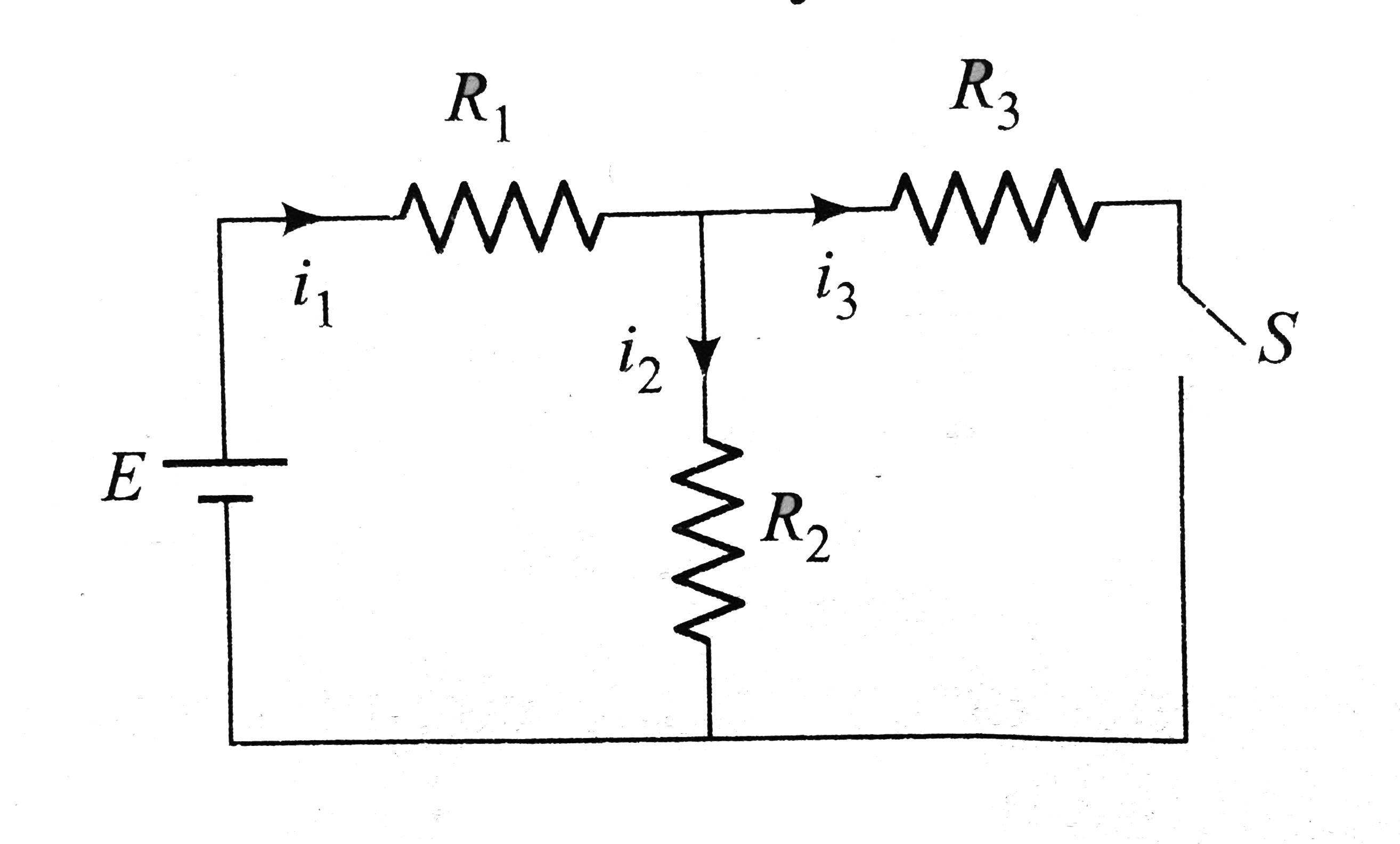
Immediately after tuning switch S on,Ai1=i2=7.5A, i3=0ABi1=i3=5A, i2=0ACi1=i2=9A, i3=0ADi1=i2=i3=0AIn the circuit shows in Fig E=15V, R1=1Ω, R2=1Ω, R3=2Ω, and L=1.5H. The currents flowing through R1,R2,and R3 are i1,i2, and i3, respectively.
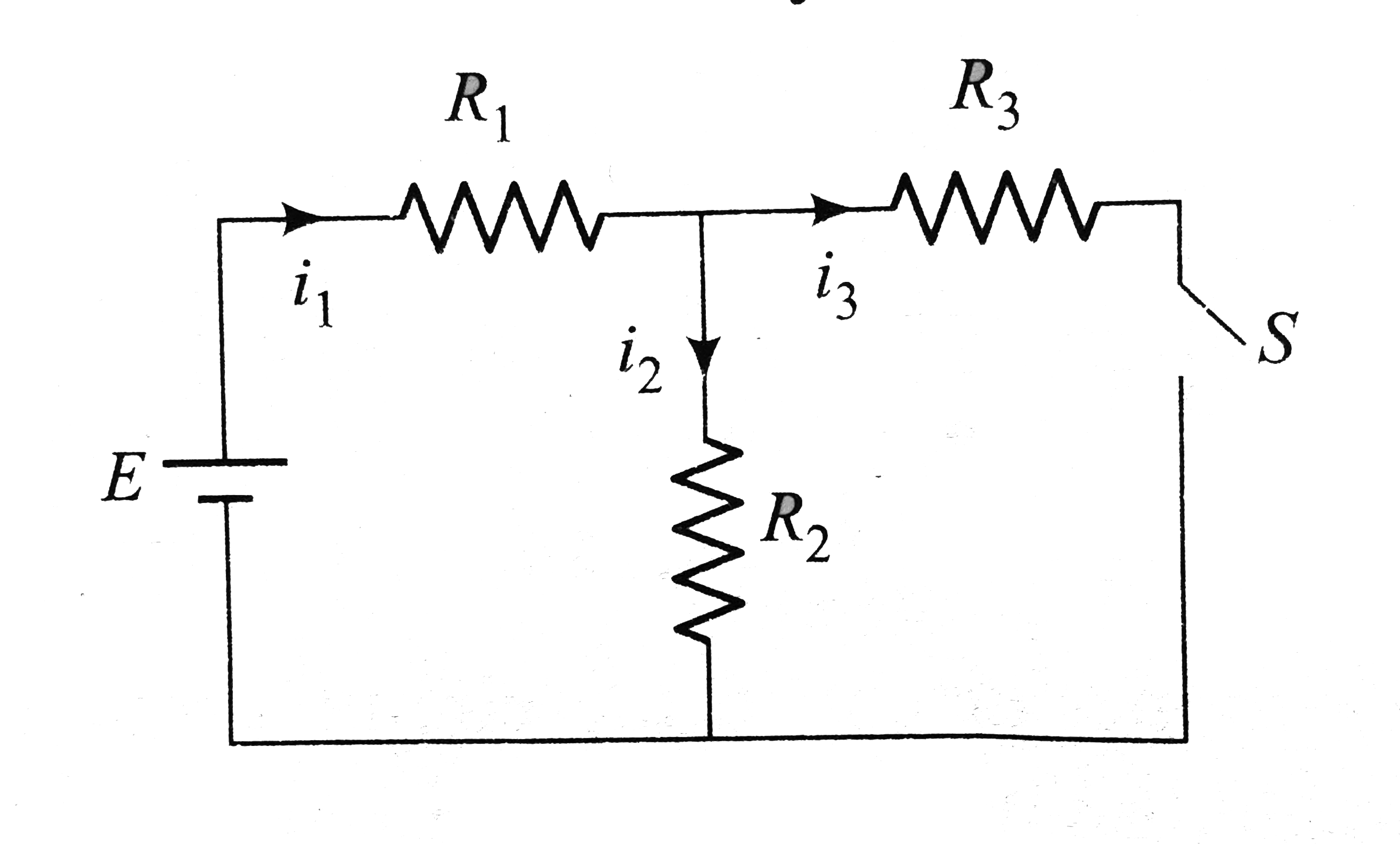
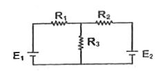
Immediately after connecting switch S,Ai3=0A and di3dt=0As−1Bi3=0A and di3dt≠0As−1Ci3=0A and the rate at which magnetic energy stored is not zeroDNone of theseIn the circuit shown below E1=4.0V,R1=2Ω,E2=6.0V,R2=4Ω and R3=2Ω. The current I1 is
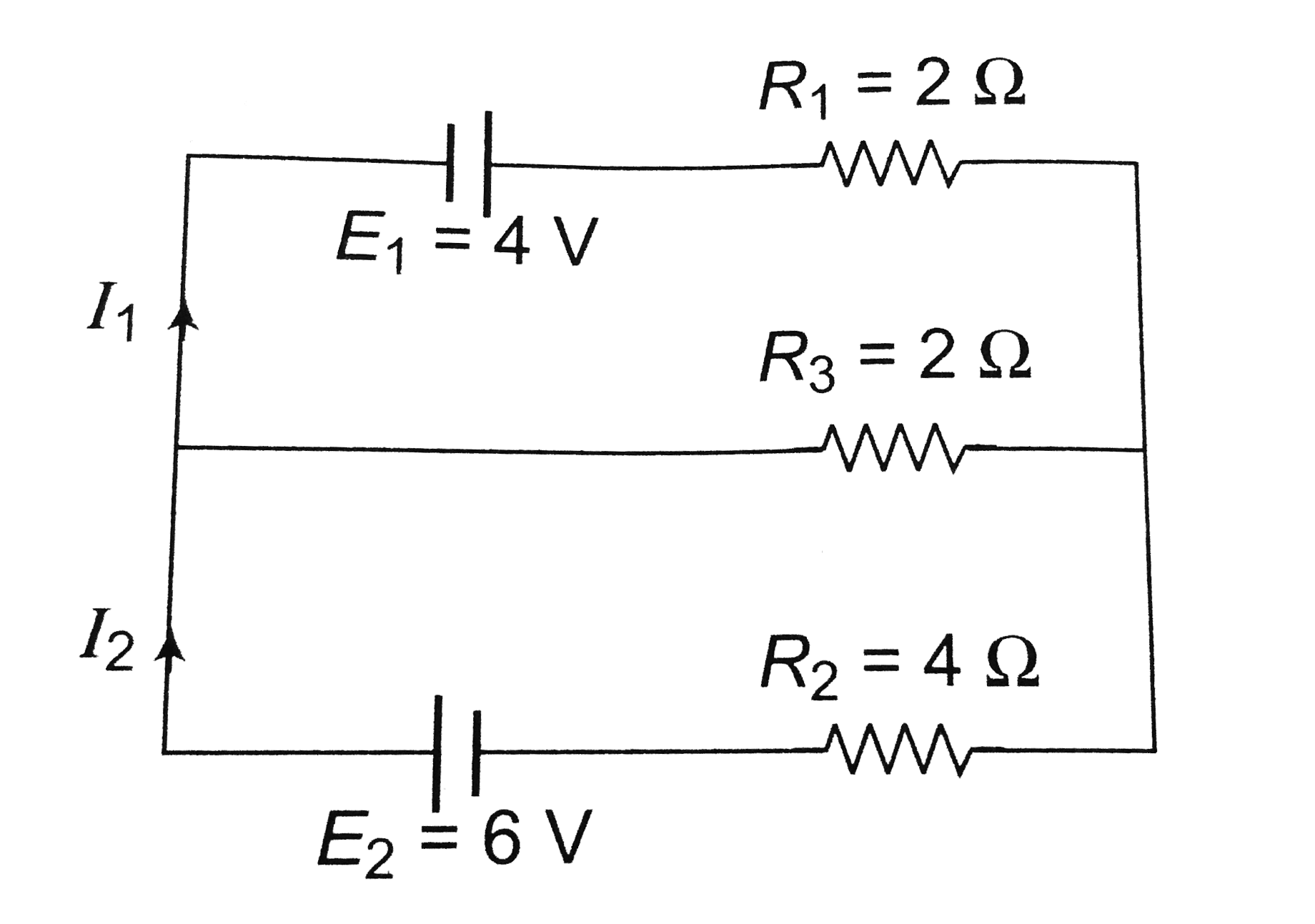 A1.6AB1.8AC1.25AD1.0A
In the circuits show ε=15V,R1=1Ω,R2=1Ω,R3=2ΩandL=15H . Find the current i1,i2,i3 (i) immediately after the switch is closed (ii) immediately after the opening from the closed position (iii) sufficiently long after , the switch is opened f rom the colsed position,
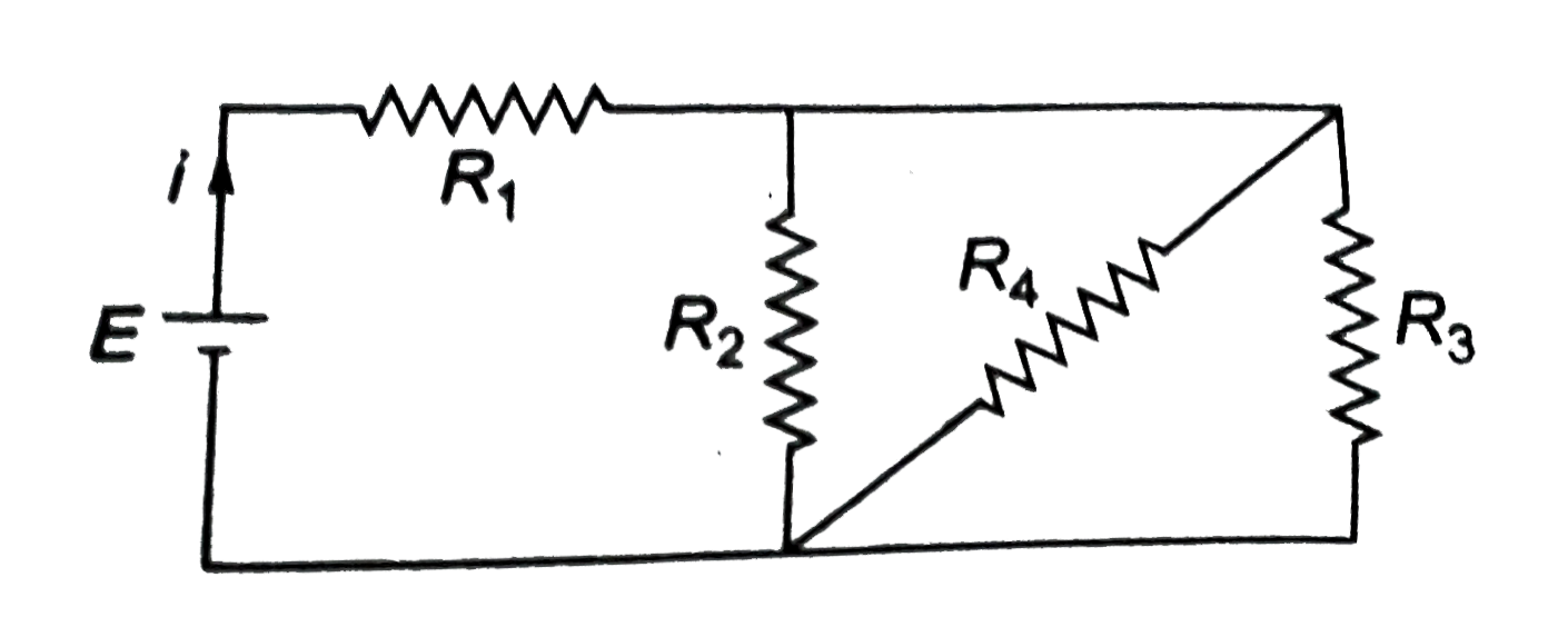
View SolutionIn the circuit given E = 6.0 volt, R1=100Ω,R2=R3=50Ω and R4=75Ω. The equivalent resistance of the circuit, in ohms is
View SolutionIn the circuit shown in adjoining fig E =10V, R1=1ΩR2=2Ω,R3=3ΩandL=2H. Calculate the value of current i1,i2andi3 immidiately after key S is closed :-
View SolutionIn the circuit shown, E1=7V,E2=7V,R1=R2=1Ω and R3=3Ω respectively. The current through the resistance R3
View SolutionIn the circuit shown in figure
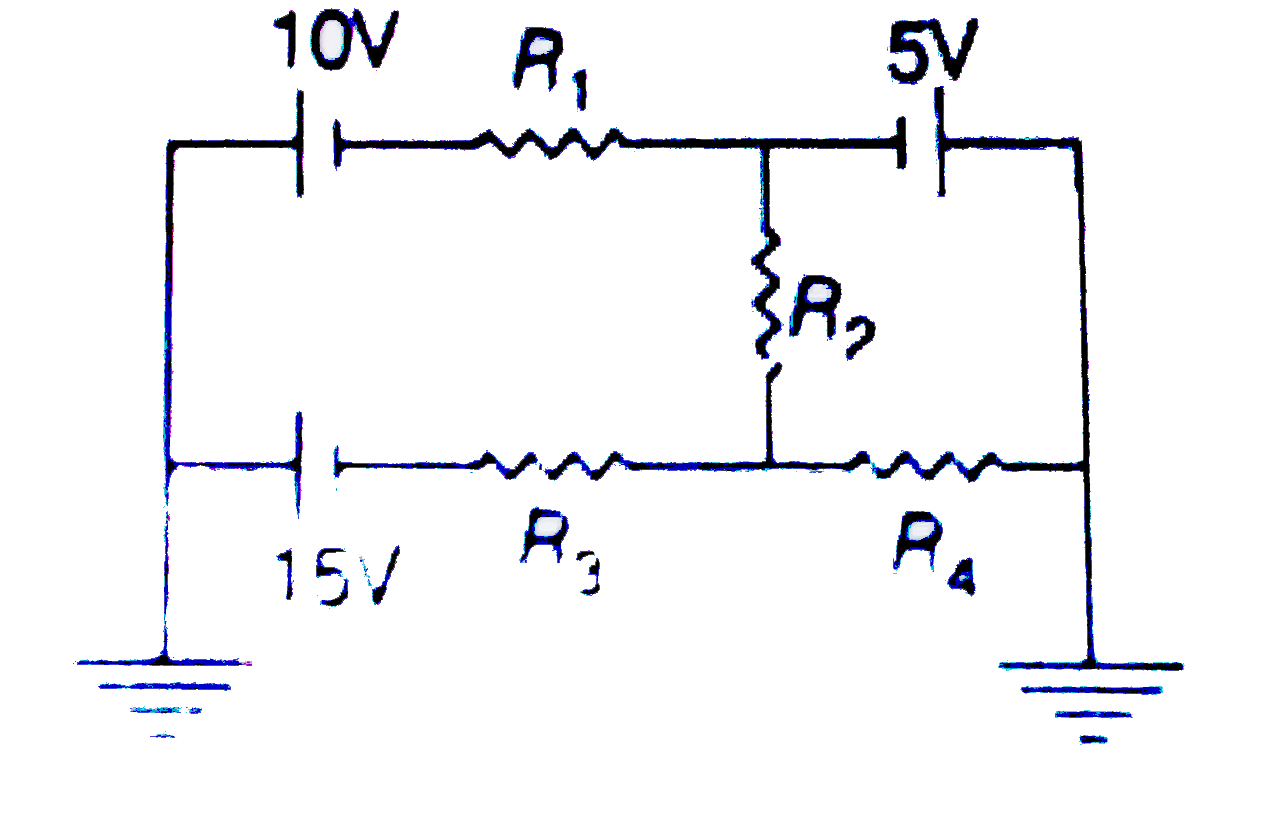
Current through R2 is zero if R4=2Ω and R3=4Ω In this case
View Solution

