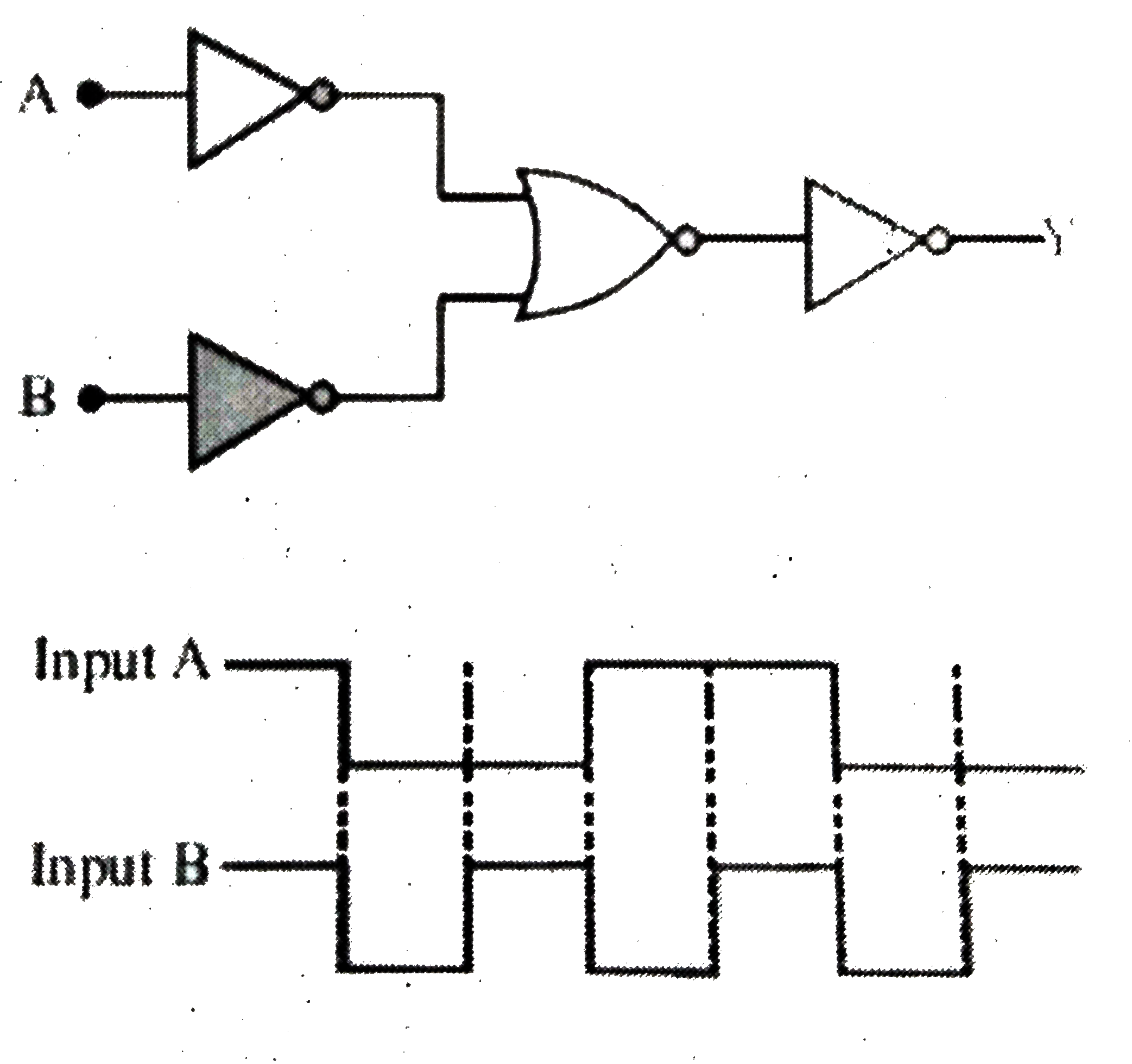
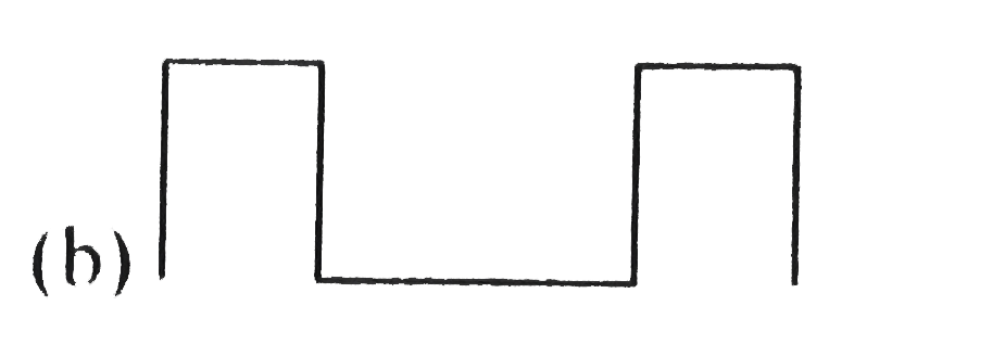
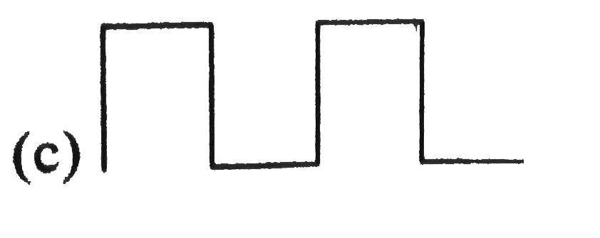
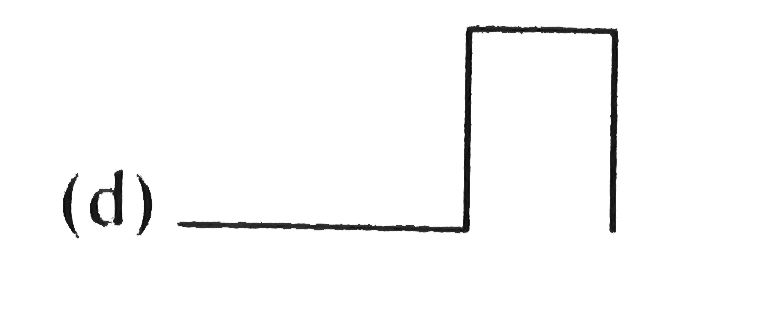
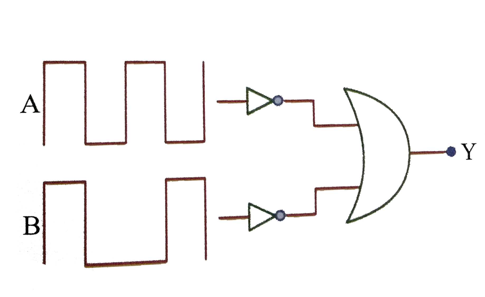
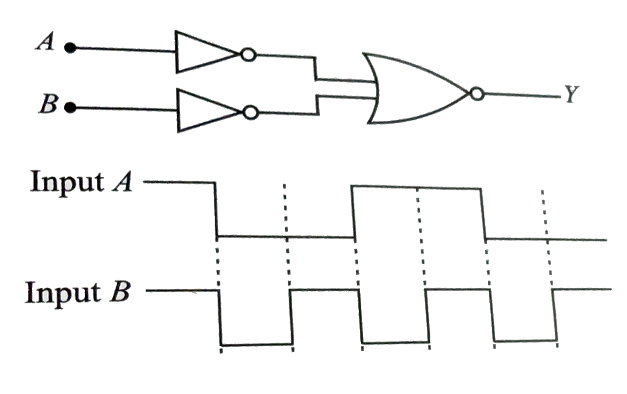
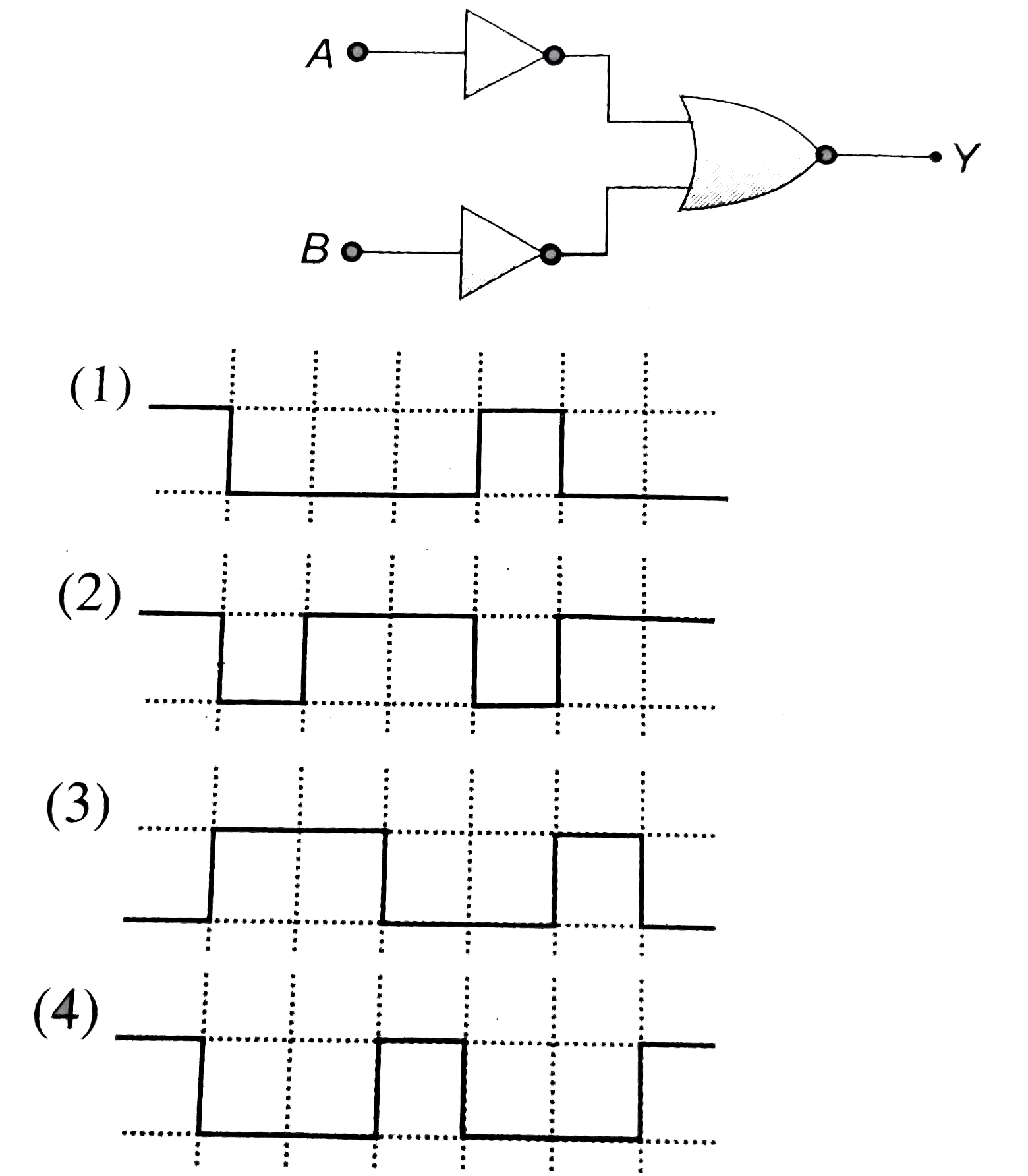
In the given circuit as shown the two input waveform A and B are applied simultaneously. The resultant waveform Y is
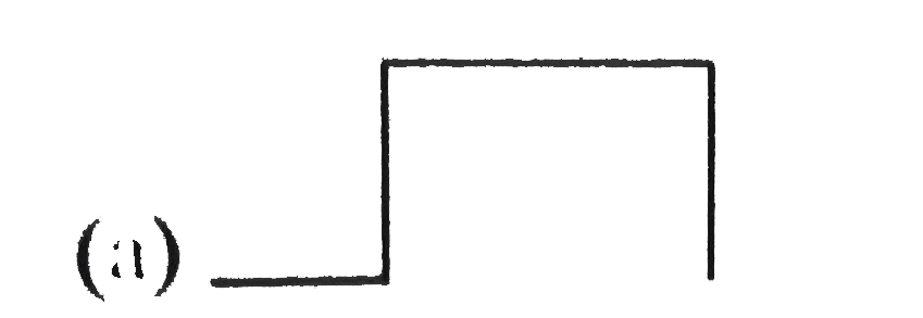
A
B
C
D
Video Solution
Text Solution
The correct Answer is:A
(1=high,0=low)
Input to A is in the sequence, 1,0,1,0.
Input to B is in the sequence, 1,0,0,1.
Sequence is inverted by NOTgate.
Thus inputs to OR gate becomes 0,1,0,1 and ouput OR gate becomes 0,1,1,1
Since for OR gate 0+1=1. hence choice (a) is correct.
|
Updated on:21/07/2023
Topper's Solved these Questions
- BOOK - A2ZCHAPTER - SEMICONDUCTOR ELECTRONICSEXERCISE - Problems Based On Mixed Concepts32videos
SEMICONDUCTOR ELECTRONICS
- BOOK - A2ZCHAPTER - SEMICONDUCTOR ELECTRONICSEXERCISE - Section B - Assertion Reasoning22videos
SEMICONDUCTOR ELECTRONICS
- BOOK - A2ZCHAPTER - SEMICONDUCTOR ELECTRONICSEXERCISE - Junction Transistor47videos
SEMICONDUCTOR ELECTRONICS
- BOOK - A2ZCHAPTER - NUCLEAR PHYSICSEXERCISE - Section D - Chapter End Test29videos
NUCLEAR PHYSICS
- BOOK - A2ZCHAPTER - SOURCE AND EFFECT OF MAGNETIC FIELDEXERCISE - Section D - Chapter End Test30videos
SOURCE AND EFFECT OF MAGNETIC FIELD
Similar Questions
Knowledge Check
- Question 1 - Select One
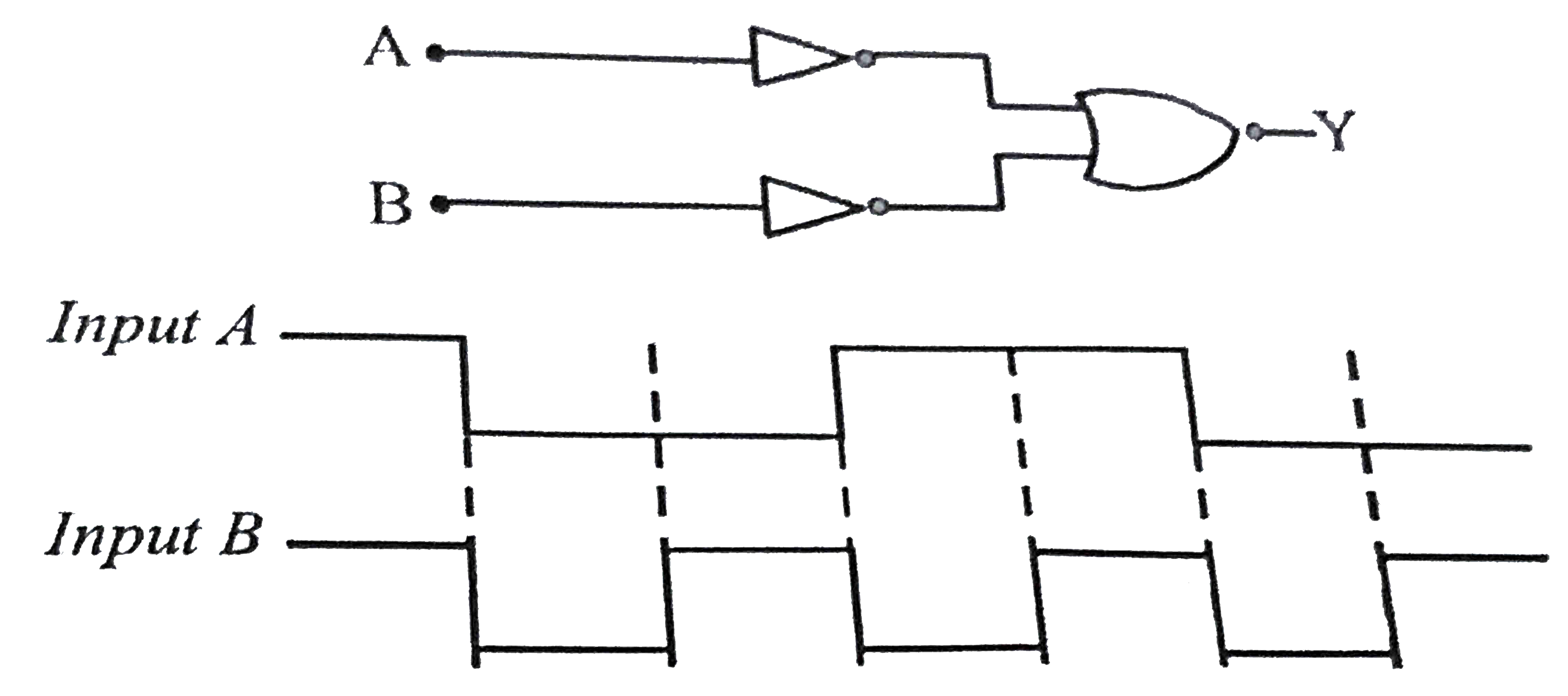
In a given circuit as shown the two input wave forms A and B are applied simultaneously.
The resultant wave format at Y is.A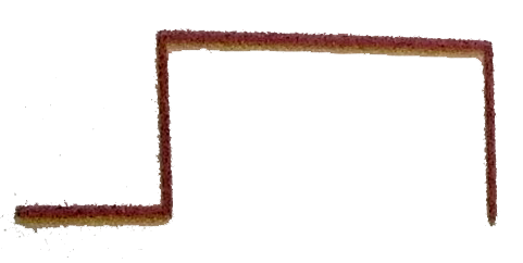 B
B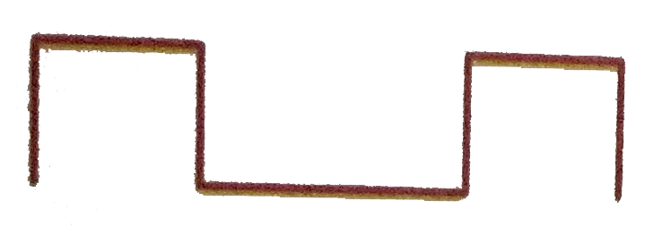 C
C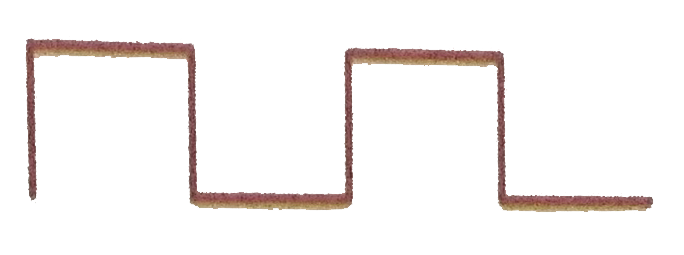 D
D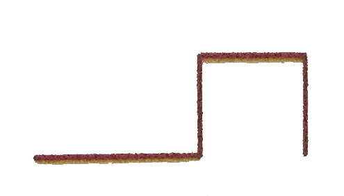
- Question 2 - Select One
In the adder circuits of two inputs
AAND gate is used for carry forward memoryBXOR gate is used for displayCBoth (1) and (2)Dnone of these - Question 3 - Select One
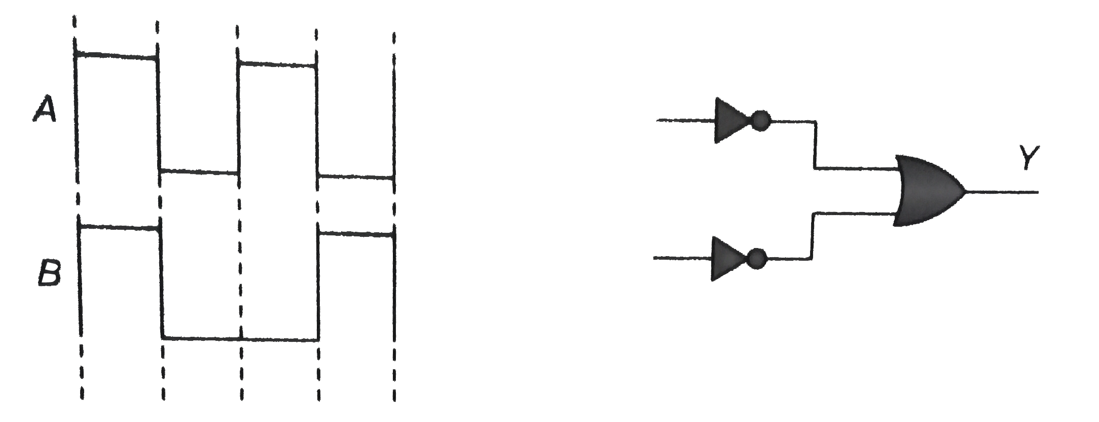
The logic circuit shown below has the inputs waveforms A and B as shown. Pick out the correct output waveform.
 A
A B
B C
C D
D
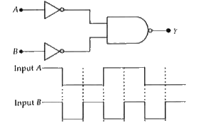
The logic circuit shown below has the input waveforms A and B as shown. Pick out the correct out put waveform.
 View Solution
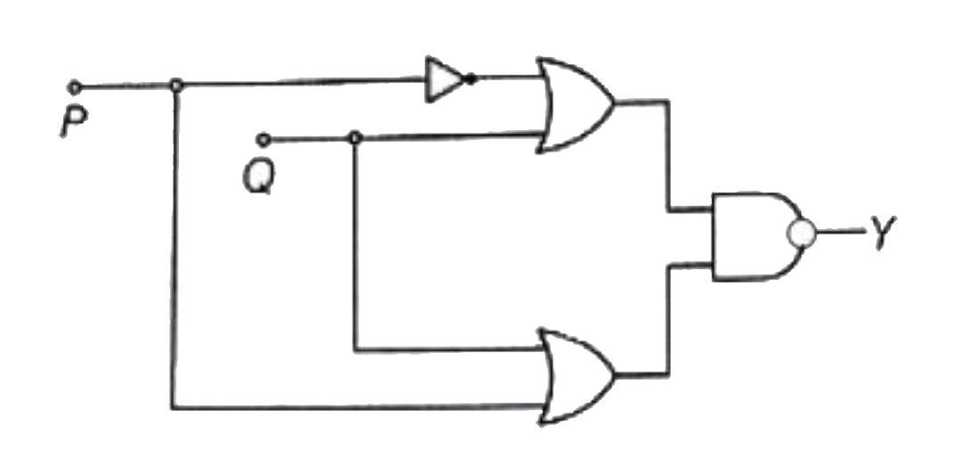
In the given circuit P and Q from the inputs. The output Y is
 View Solution
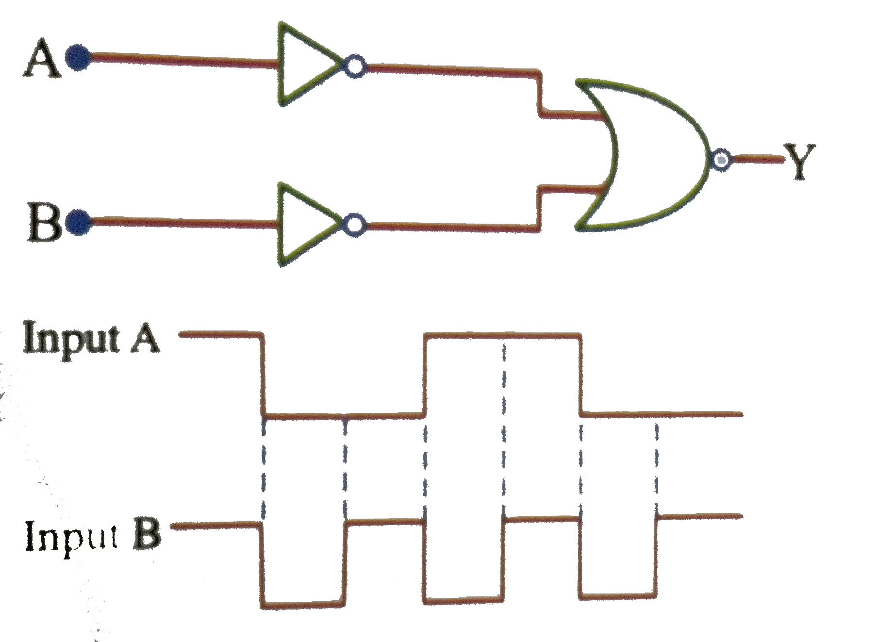
The logic circuit shown below has the input waveforms 'A' and 'B' as shown. Pick out the correct output waveform
 .View Solution
The logic circuit shown belows has the input waveforms 'A' and 'B' as shown. Pick out the correct output waveform
 View Solution
The logic circuit shown below has the input waveform 'A' and 'B' as shown. Pick out the correct output waveform
_E01_490_Q01.png)
Output is :-View Solution


