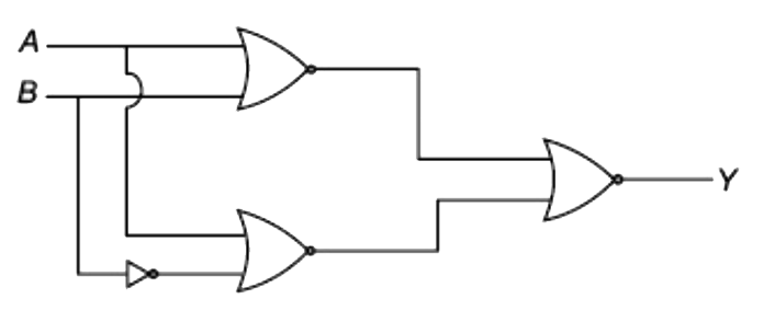
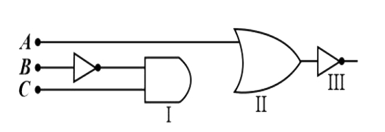
The output (X) of the logic circuit shown in figure will be

A
X=¯¯¯¯¯¯¯A.¯¯¯¯¯¯B
B
X=¯¯¯¯¯¯¯¯A.B
C
X=A.B
D
X=¯¯¯¯¯¯¯¯¯¯¯A+B
Video Solution
Text Solution
The correct Answer is:C
X=¯¯¯¯¯¯¯¯¯¯¯¯AB=A.B
|
Topper's Solved these Questions
- SEMICONDUCTOR ELECTRONICSBook:A2ZChapter:SEMICONDUCTOR ELECTRONICSExercise:AIIMS Questions
Explore 38 Videos
- SEMICONDUCTOR ELECTRONICSBook:A2ZChapter:SEMICONDUCTOR ELECTRONICSExercise:Assertion Reason
Explore 18 Videos
- SEMICONDUCTOR ELECTRONICSBook:A2ZChapter:SEMICONDUCTOR ELECTRONICSExercise:Section B - Assertion Reasoning
Explore 22 Videos
- NUCLEAR PHYSICSBook:A2ZChapter:NUCLEAR PHYSICSExercise:Section D - Chapter End Test
Explore 29 Videos
- SOURCE AND EFFECT OF MAGNETIC FIELDBook:A2ZChapter:SOURCE AND EFFECT OF MAGNETIC FIELDExercise:Section D - Chapter End Test
Explore 30 Videos
Similar Questions
Knowledge Check
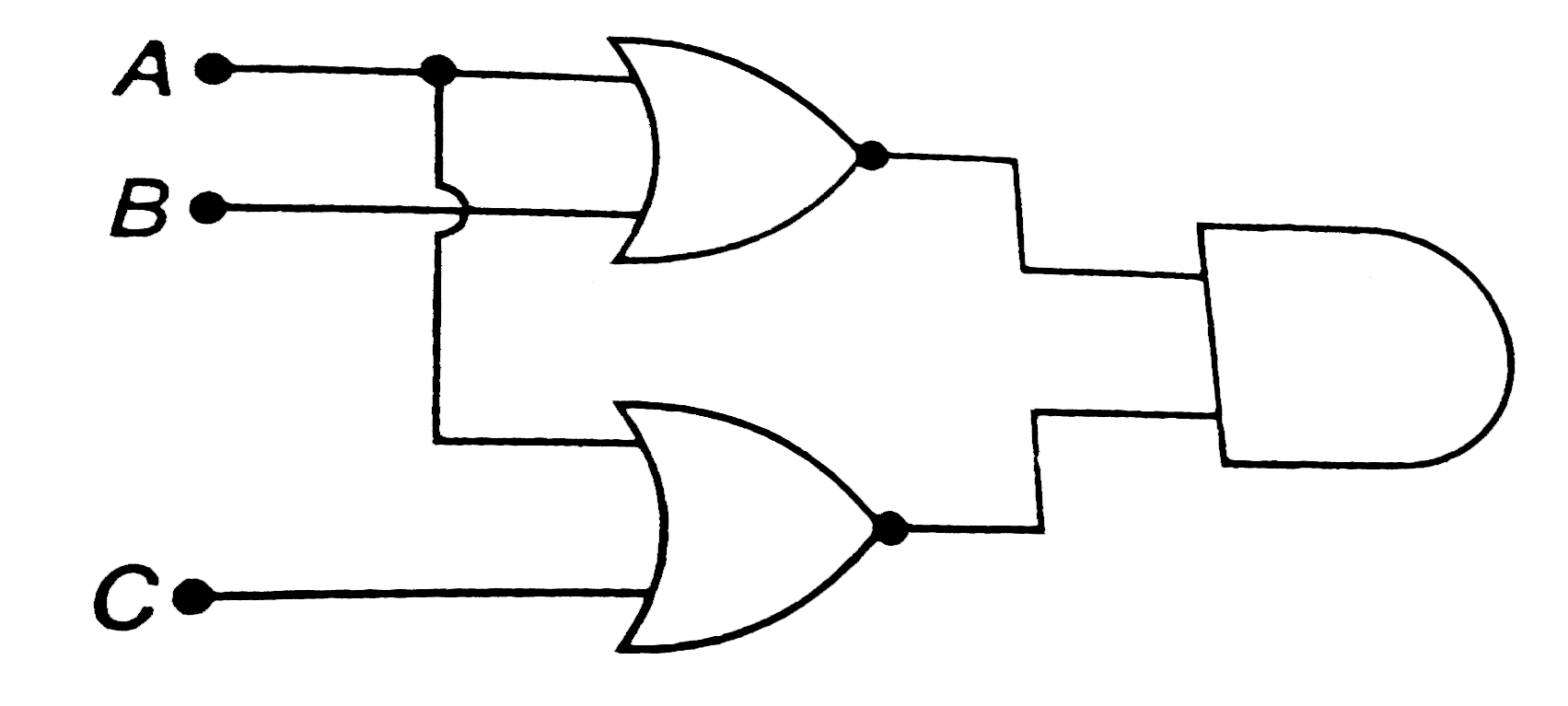
The output Y of the logic circuit as shown in figure is
 A(A+B)⋅¯¯¯CB(A+C)⋅¯¯¯CC(B+C)⋅¯¯¯ADA+B+C
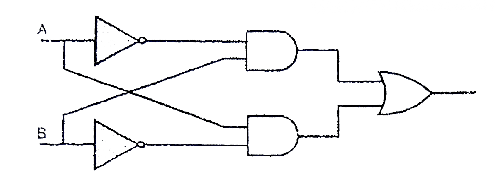
The output Y of the logic circuit as shown in figure is best represents as
 A¯¯¯A+¯¯¯¯¯¯¯¯¯B⋅CBA+¯¯¯B⋅CC¯¯¯¯¯¯¯¯¯¯¯¯¯¯¯¯¯A+B⋅CD¯¯¯¯¯¯¯¯¯¯¯¯¯¯¯¯¯A+¯¯¯B⋅C
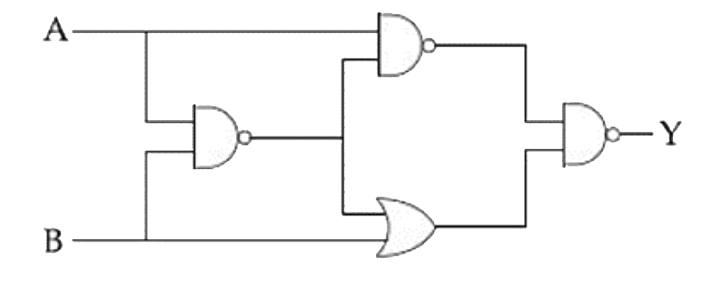
The outpout Y of the logic circuit shown in figure is best represented as
 A¯¯¯A+¯¯¯B.¯¯¯CB¯¯¯A+¯¯¯B.CC¯¯¯A+B.¯¯¯CD(¯¯¯A+¯¯¯B)C
