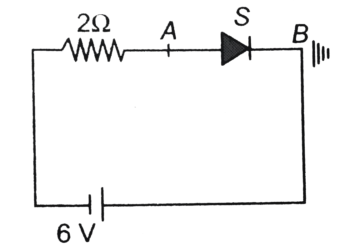
The diode shown in the circuit is a silicon diode. The potential difference between the points A and B will be
A
6V
B
0.6V
C
0.7V
D
0V
Video Solution
Text Solution
The correct Answer is:A
In the given condition diode is in reverse biasing so it acts as open circuit. Hence potential difference between A and B is 6V.
|
Updated on:21/07/2023
Topper's Solved these Questions
- BOOK - A2ZCHAPTER - SEMICONDUCTOR ELECTRONICSEXERCISE - Assertion Reason18videos
SEMICONDUCTOR ELECTRONICS
- BOOK - A2ZCHAPTER - SEMICONDUCTOR ELECTRONICSEXERCISE - SECTION -D1videos
SEMICONDUCTOR ELECTRONICS
- BOOK - A2ZCHAPTER - SEMICONDUCTOR ELECTRONICSEXERCISE - AIPMT/NEET Questions77videos
SEMICONDUCTOR ELECTRONICS
- BOOK - A2ZCHAPTER - NUCLEAR PHYSICSEXERCISE - Section D - Chapter End Test29videos
NUCLEAR PHYSICS
- BOOK - A2ZCHAPTER - SOURCE AND EFFECT OF MAGNETIC FIELDEXERCISE - Section D - Chapter End Test30videos
SOURCE AND EFFECT OF MAGNETIC FIELD
Similar Questions
Knowledge Check
- Question 1 - Select One
In the circuit shown in figure-3.331, the potential difference between points A and Bis :
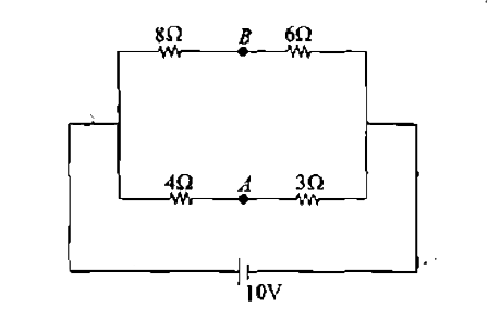 A207VB407VC107VDZero
 - Question 2 - Select One
Potential difference between the points B and E of the circuit is -
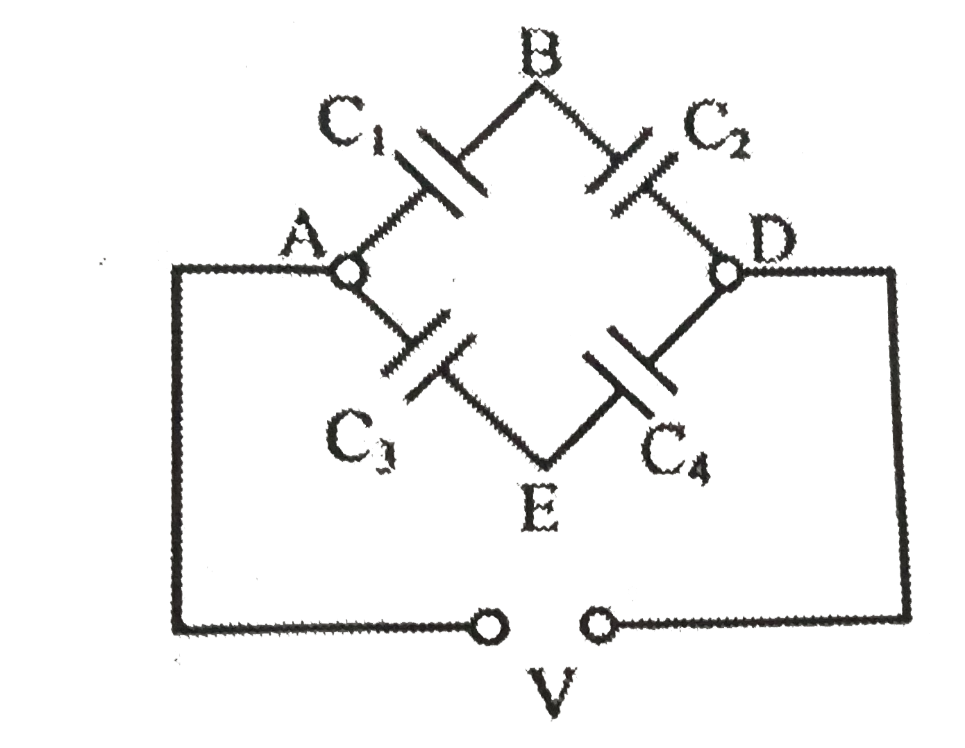 A(C2−C1)VB(C4−C3)VC{C2C3−C1C4C1+C2+C3+C4}D{C1C4−C2C3(C1+C2)(C3+C4)}
 - Question 3 - Select One
In given circuit , the potential difference between points A and B is
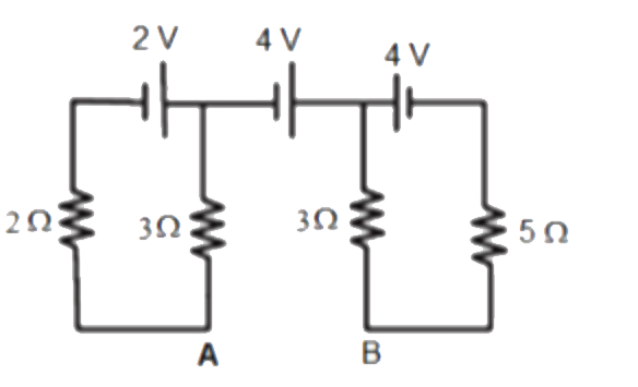 A10 VB15 VC20 VD5V
What is the potential difference between points A and B in the circuit shown?
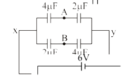 View Solution
In the circuit shown, the potential difference between A and B is:
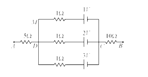 View Solution
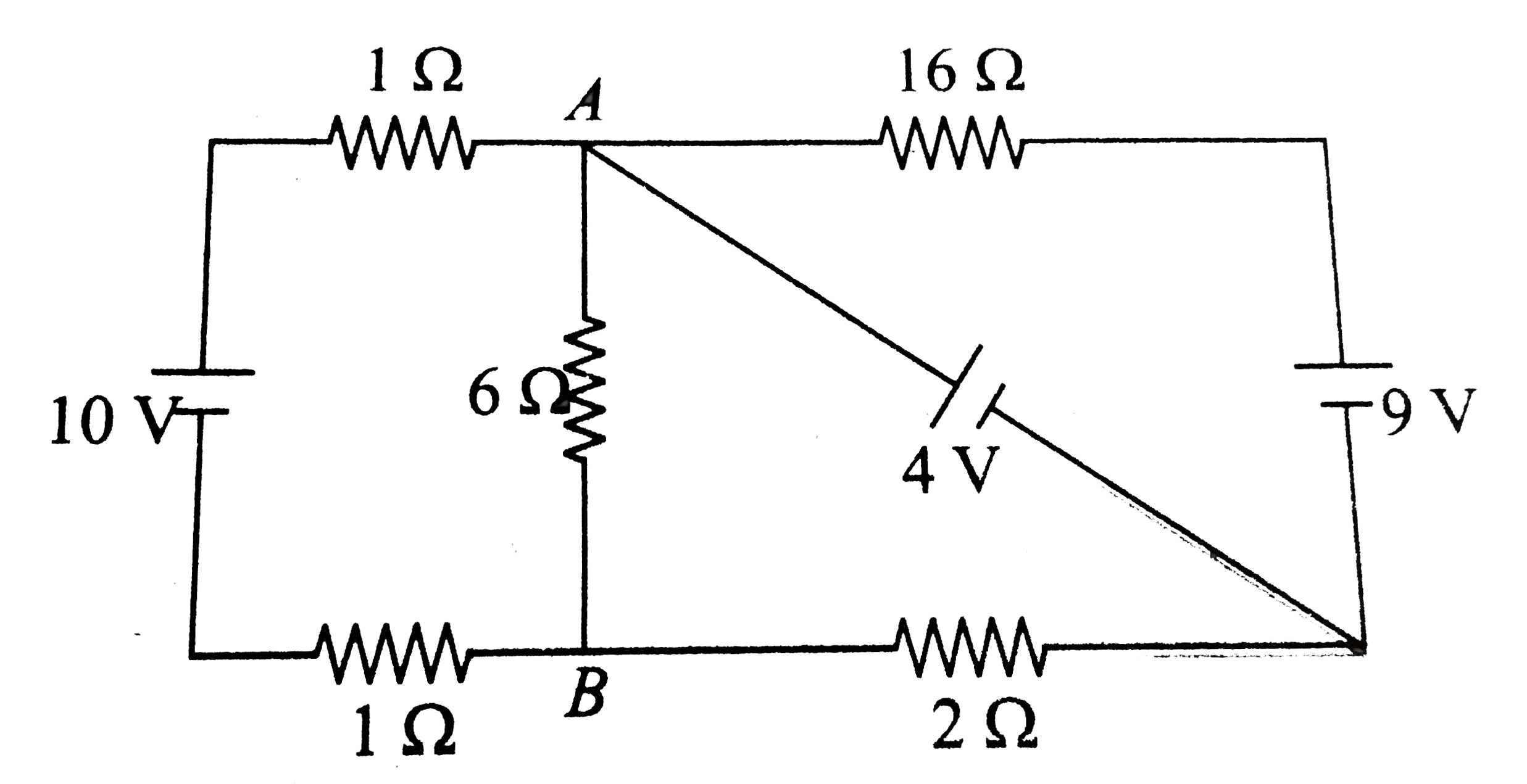
Find the potential difference (inV) between points A and B shown in the circuit.
 View Solution
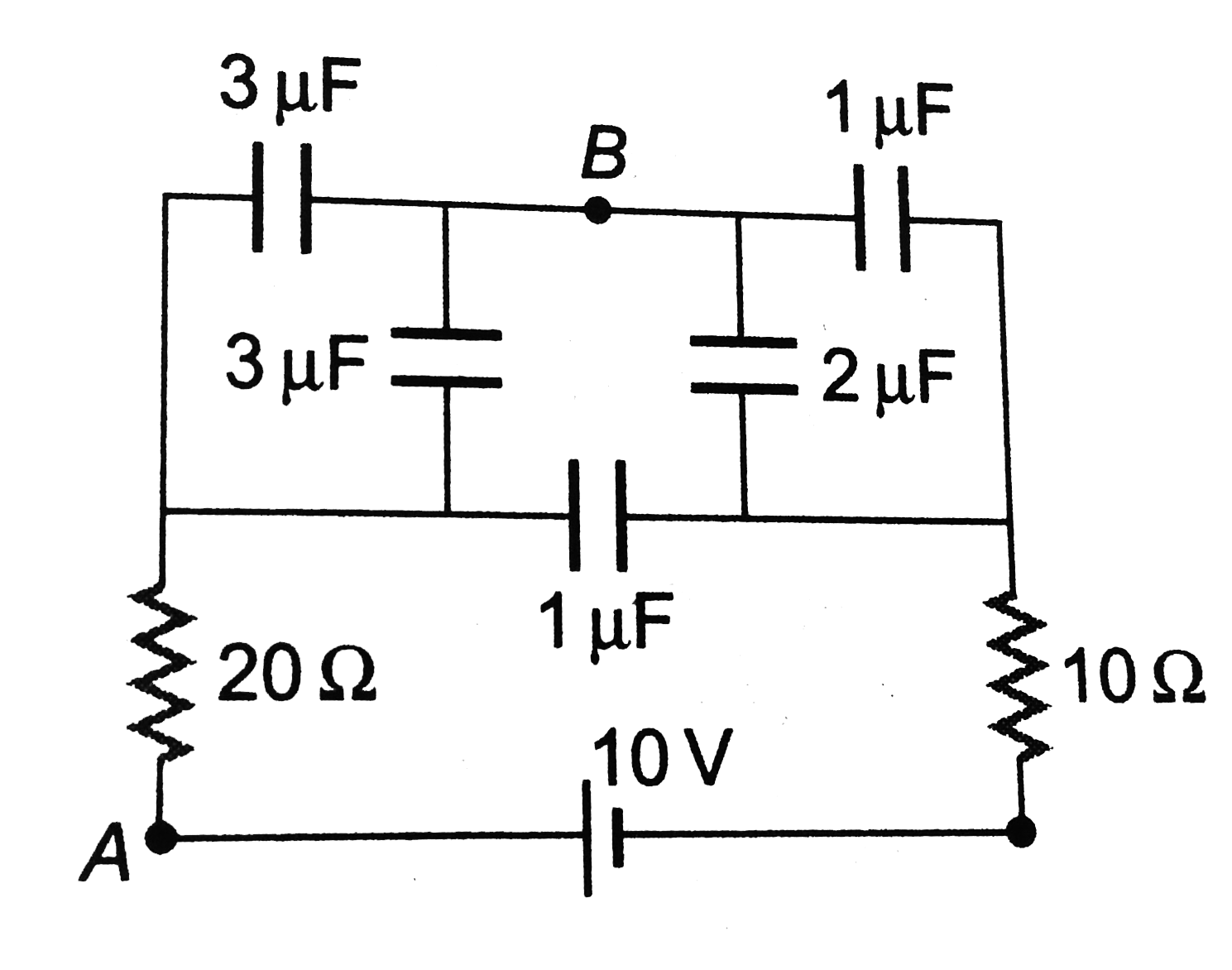
In the circuit shown in figure potential difference between the points A and B in the steady state is
 View Solution
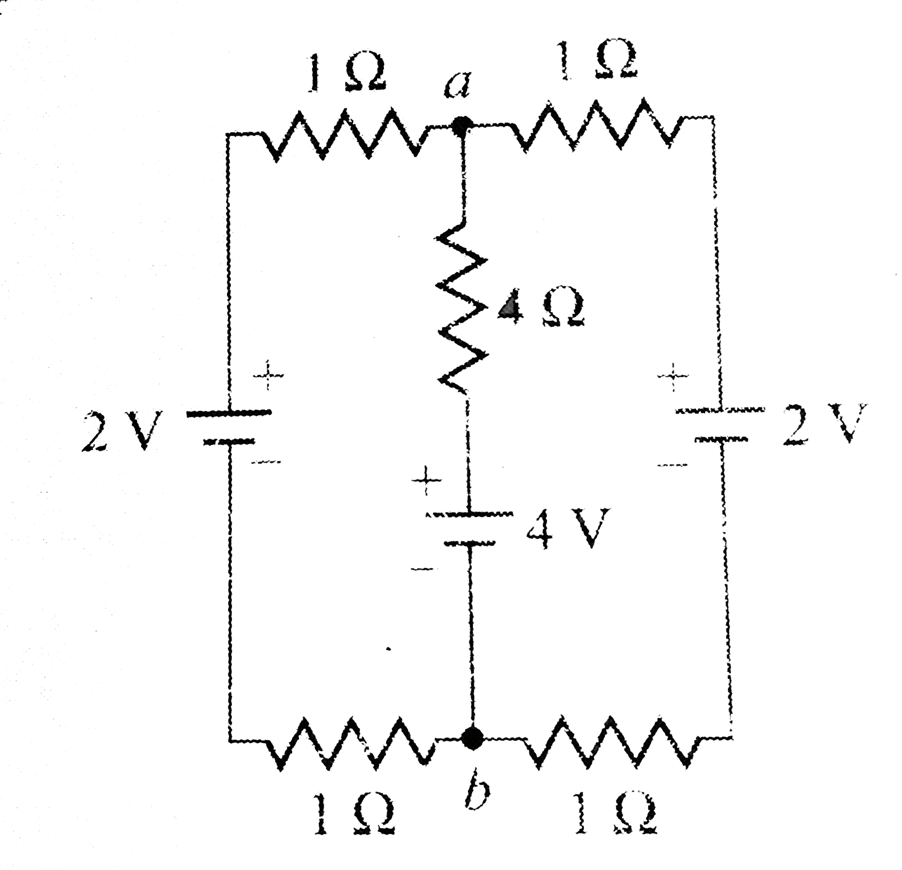
For the circuit given in figure, find the potential difference between points a and b.
 View Solution


