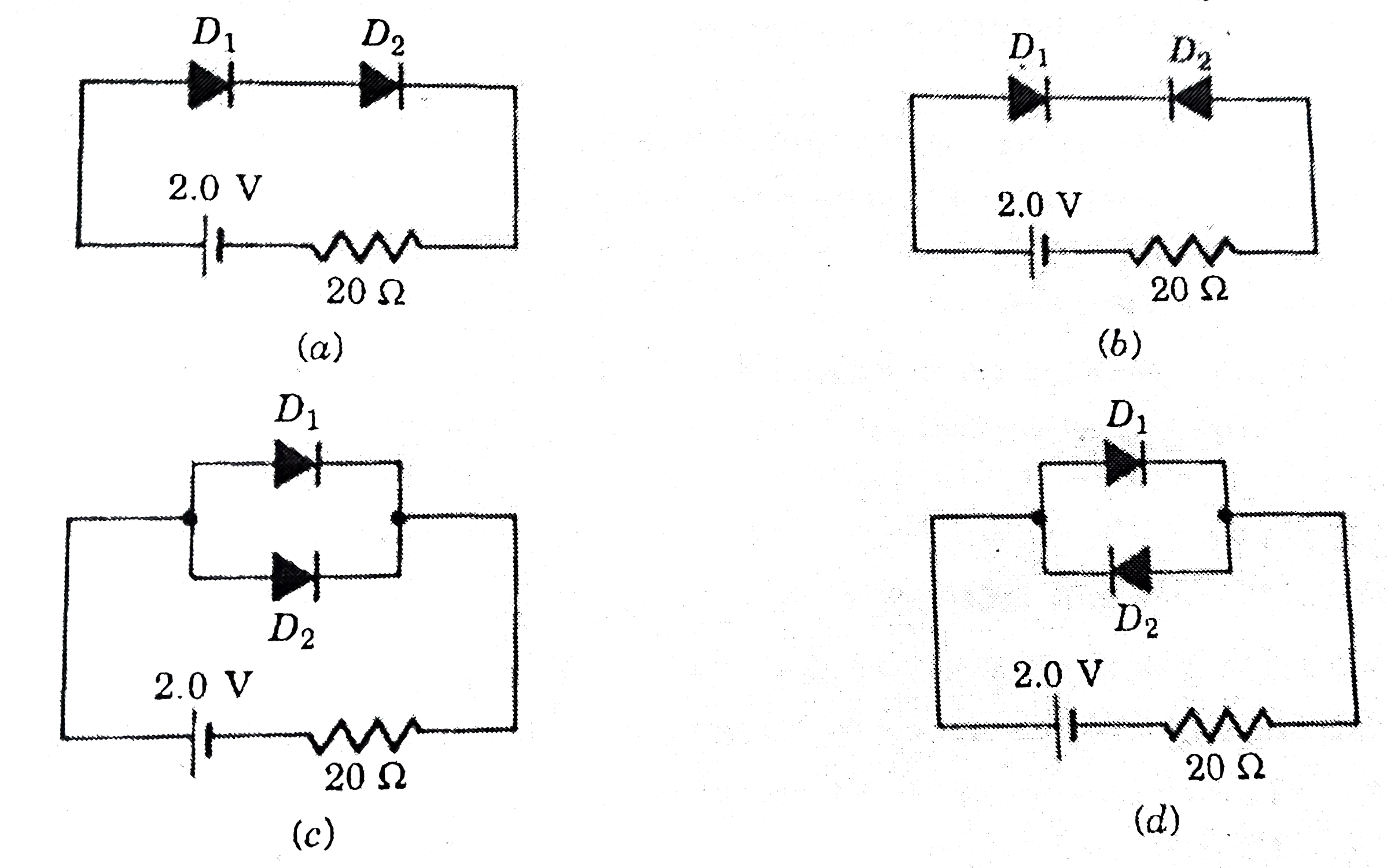
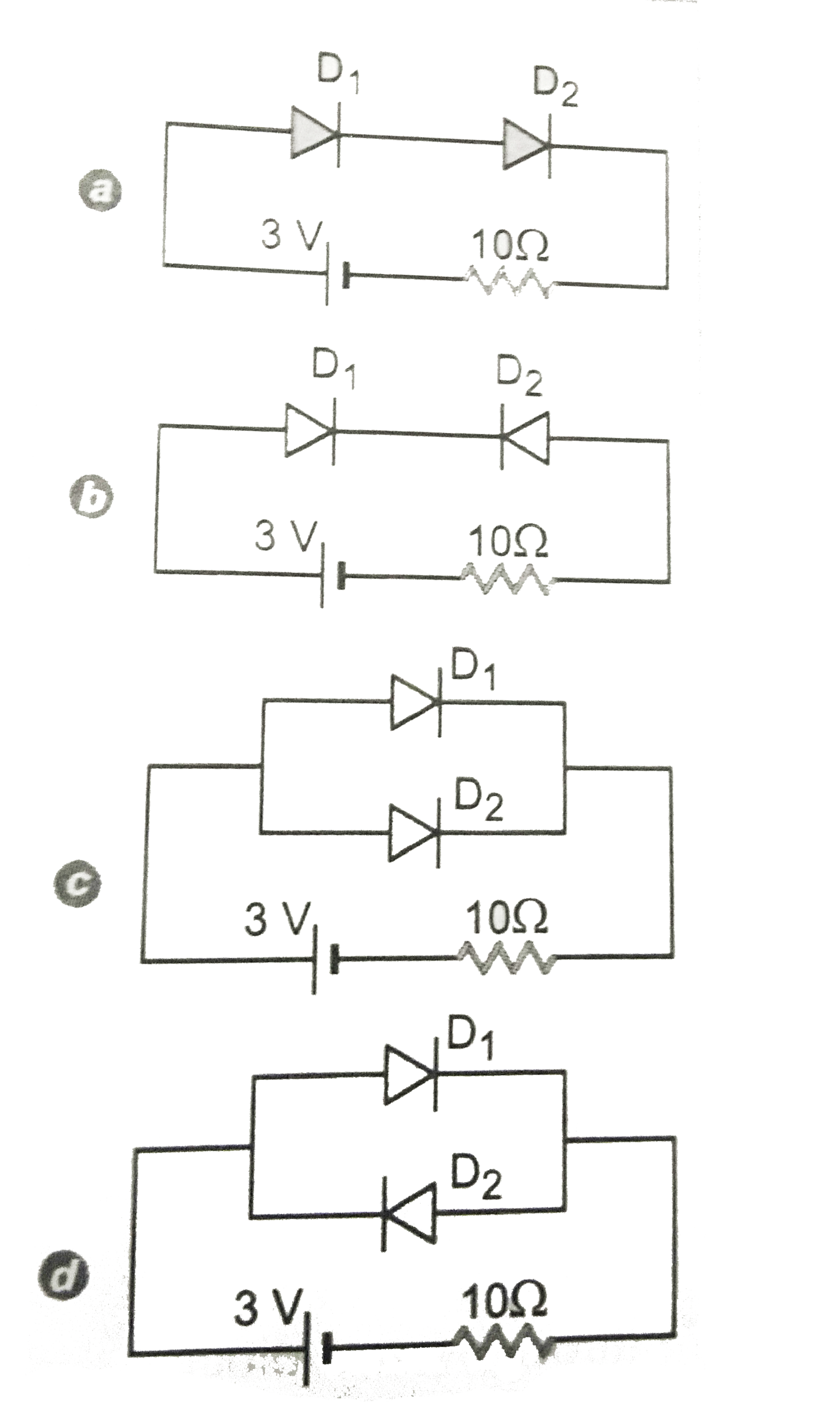
Determine the current through the resistancees of the circuit shown in Fig.. The each p-n junction used is ideal one.
Video Solution
Text Solution
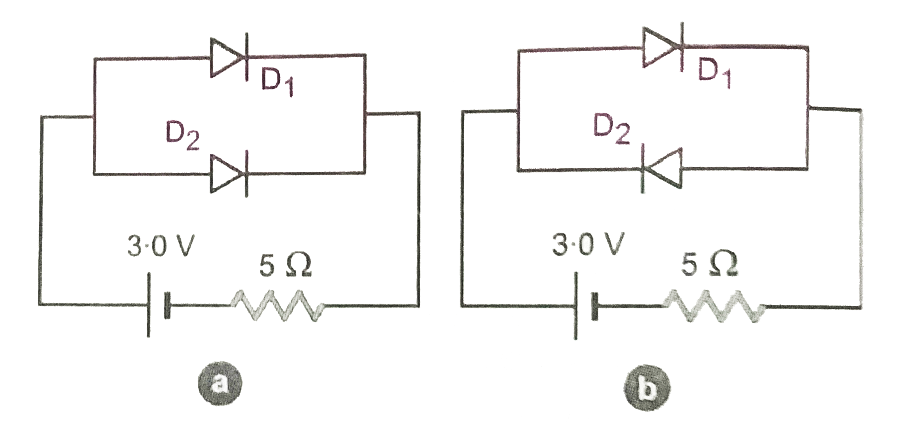
In Fig., junction diode, D1 and D2 are forward biased and offer zero resistance.
Current in the circuit, I=3.05=0.6A
In Fig, junction diode, D1 is forward biased, its resistance in circuit is zero. Junction diode D2 is reverse biased, its resistance is infinity. Therefore, current in
remaining circuit, I′=3.05=0.6A
|
Topper's Solved these Questions
- ELECTRONIC DEVICESBOOK - PRADEEPCHAPTER - ELECTRONIC DEVICESEXERCISE - SAMPLE PROBLEM
2 Videos
- ELECTRONIC DEVICESBOOK - PRADEEPCHAPTER - ELECTRONIC DEVICESEXERCISE - CONCEPTUAL PROBLEMS
1 Videos
- ELECTROMAGNETIC WAVESBOOK - PRADEEPCHAPTER - ELECTROMAGNETIC WAVESEXERCISE - II Focus multiple choice question
5 Videos
- ELECTROSTATICSBOOK - PRADEEPCHAPTER - ELECTROSTATICSEXERCISE - ASSERTION-REASON TYPE QUESTIONS
2 Videos
Similar Questions
Knowledge Check
The current through the ideal diode as shown in the is
 A0AB0.02AC0.04AD0.06A
The current through the 8Ω resistor (shown in fig.) is
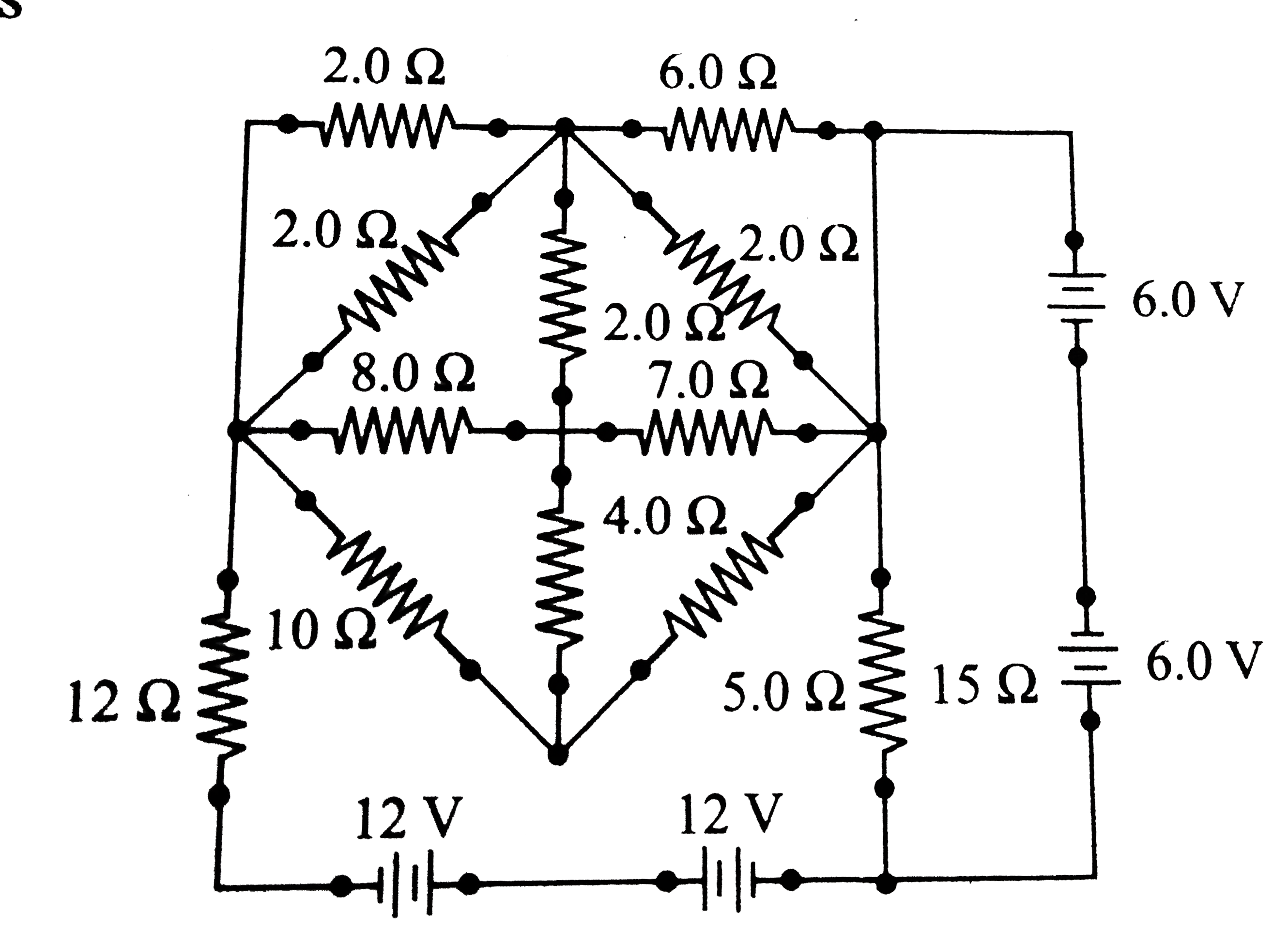 A4AB2ACzeroD2.5A
In the circuit shown in figure the current through
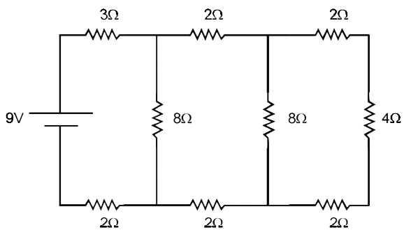 Athe 3Ω resistor is 0.50 A.Bthe 3Ω resistor is 0.25ACthe 4Ω is 0.50ADthe 4Ω resistor is 0.25A.
The current through the battery shown in the circuit is
View SolutionFind the current in each resistor in the circuit as shown in fig.
View SolutionFind the total current in the circuits shown in Fig. , , and . Each diode used is ideal
View SolutionDetermine the current in each branch of the network shown in Fig. 3.24
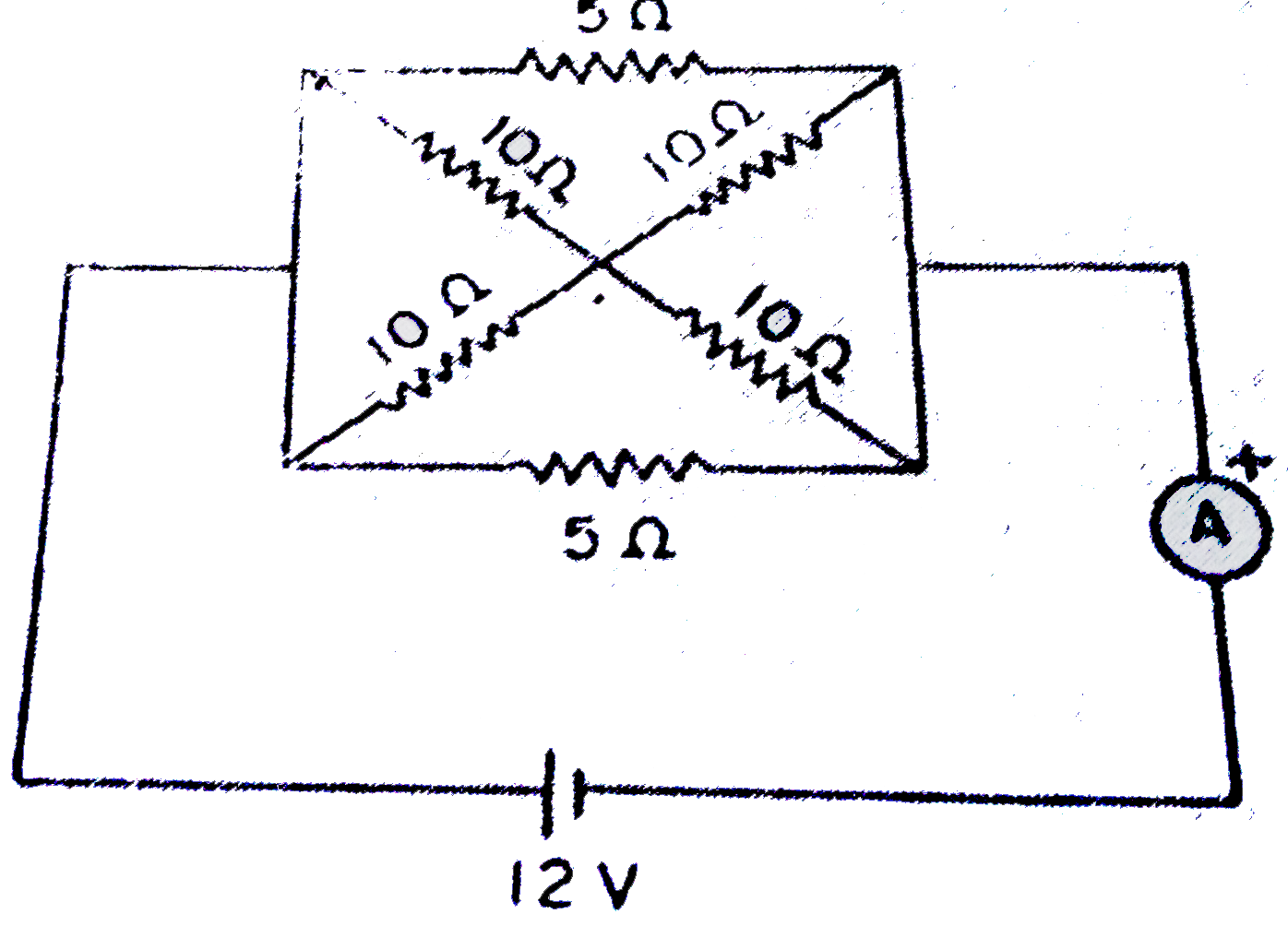
View SolutionCalculate the current shown by the ammeter A in the circuit shown in Fig. 4.47.
View Solution

