The input wave form for NOT gate is shown in Fig.Draw the output wave form of this gate.
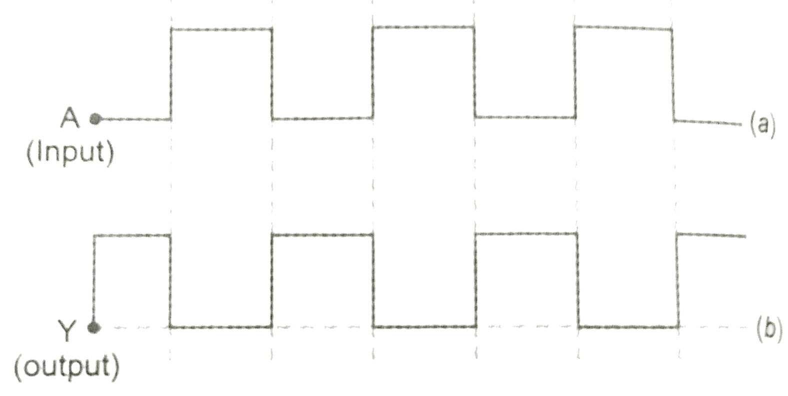
For NOT gate, the Boolean expression is y=¯¯¯A. Thus the output wave from is as shown in Fig.
Topper's Solved these Questions
- BOOK - PRADEEPCHAPTER - ELECTRONIC DEVICESEXERCISE - SAMPLE PROBLEM2videos
ELECTRONIC DEVICES
- BOOK - PRADEEPCHAPTER - ELECTRONIC DEVICESEXERCISE - CONCEPTUAL PROBLEMS1videos
ELECTRONIC DEVICES
- BOOK - PRADEEPCHAPTER - ELECTROMAGNETIC WAVESEXERCISE - II Focus multiple choice question5videos
ELECTROMAGNETIC WAVES
- BOOK - PRADEEPCHAPTER - ELECTROSTATICSEXERCISE - ASSERTION-REASON TYPE QUESTIONS2videos
ELECTROSTATICS
Similar Questions
Knowledge Check
- Question 1 - Select One
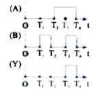
The input and the output wave form of a logic gate is shown in diagraam, then identify the logic gate :
 AAND gateBOR gateCNAND gateDNOT gate
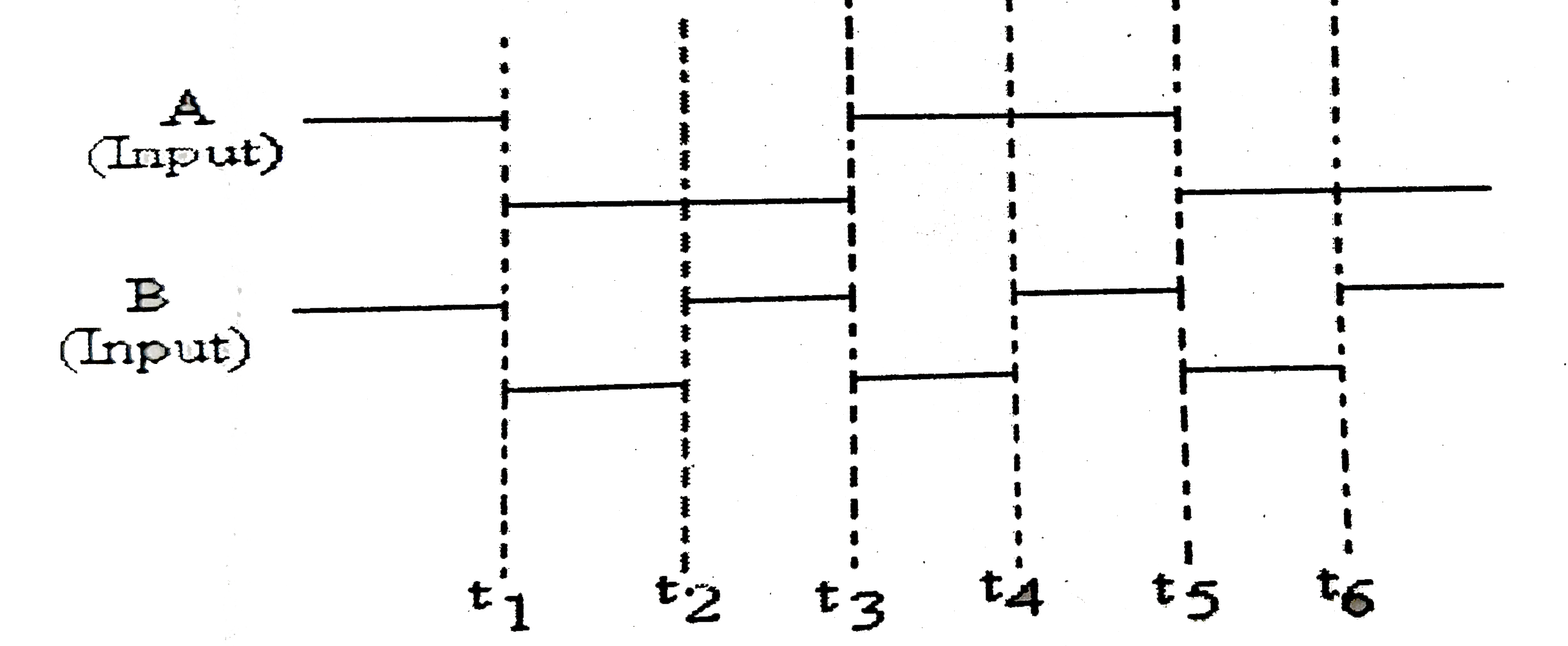
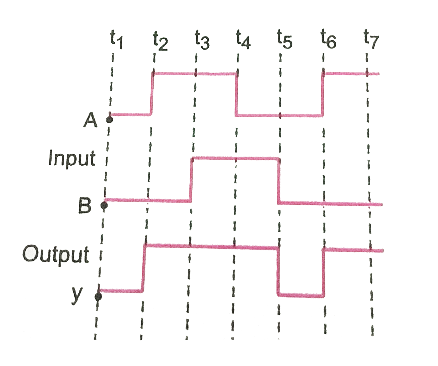
The Fig shown input waveforms A and B to a logic gate. Draw the output waveform for an OR gate. Write the truth table for this logic gate and draw its logic symbol.
 View Solution
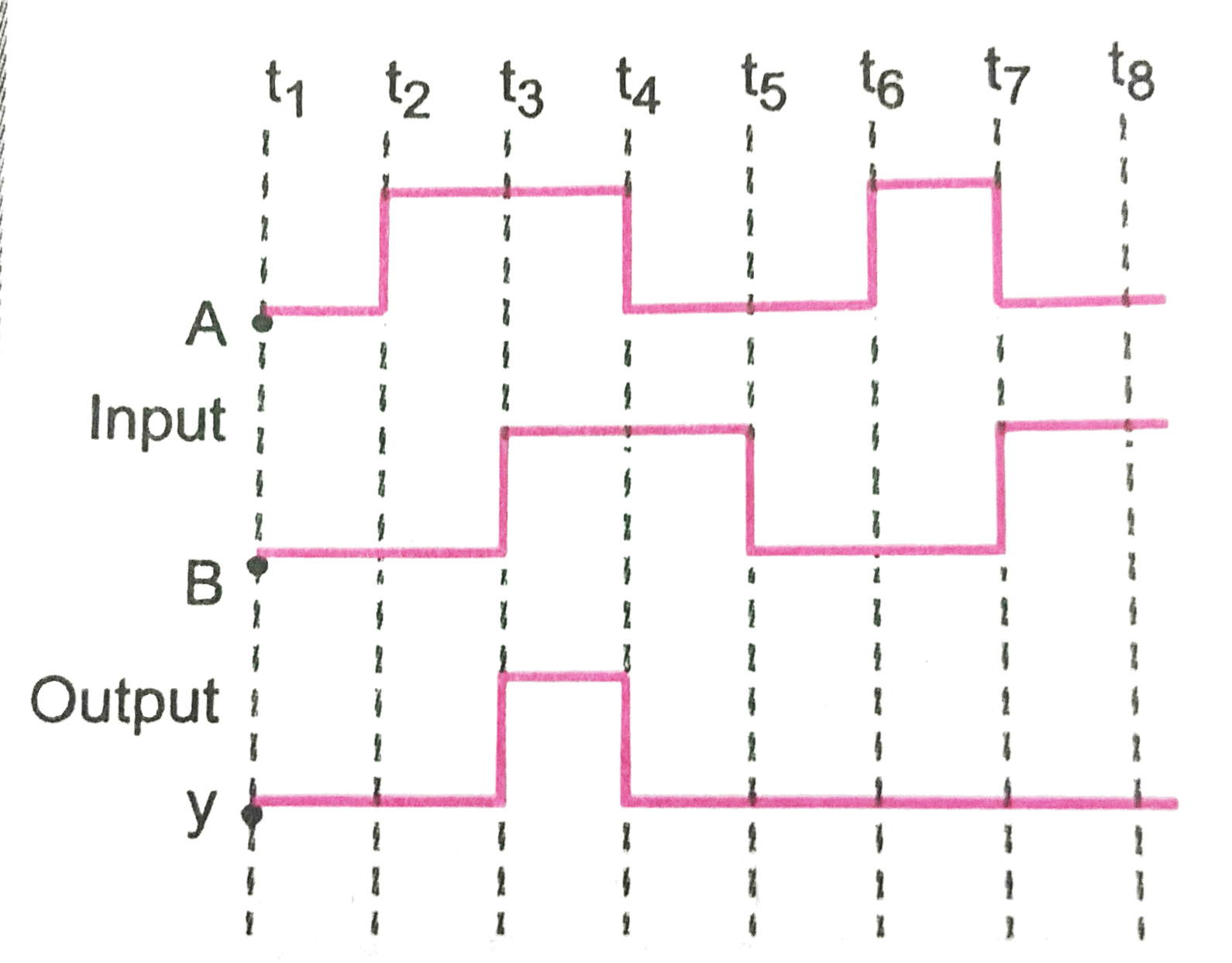
The Fig.shows the input wavwforms A and B for 'AND' gate. Draw the output waveform and write the truth table for this logic gate.
 View Solution
Using the wave forms of the input A and B, draw the output waveform of the given logic circuit . Identify the logic gate obtained . Write also the truth table.
 View Solution
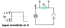
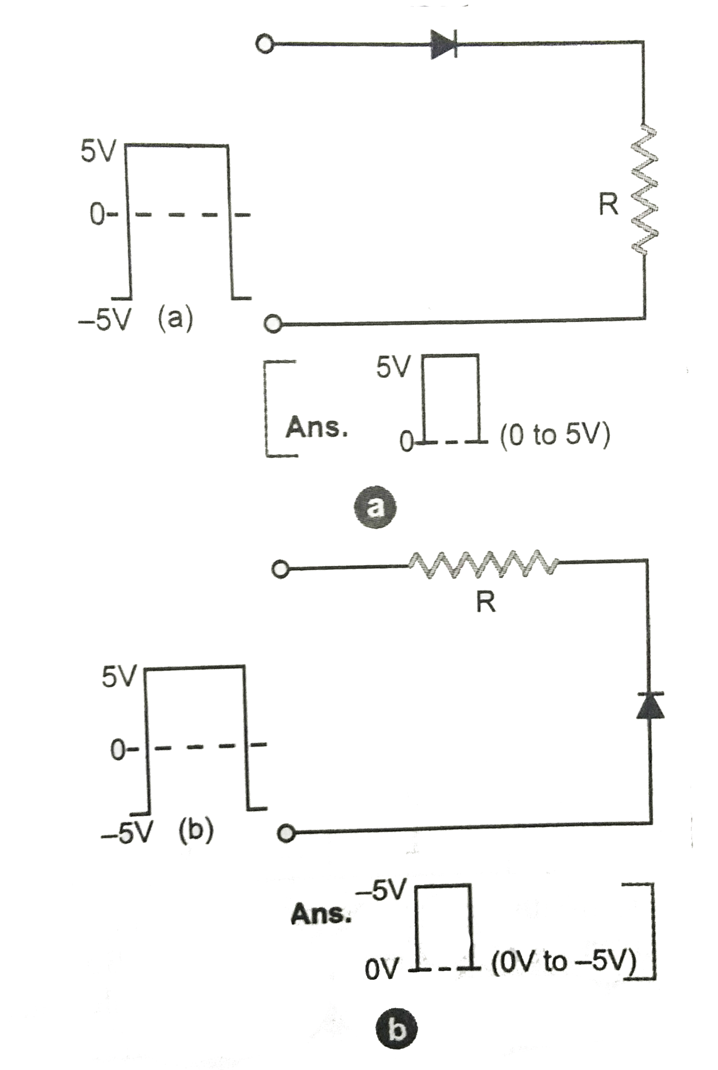
In the following circuit, if the input wave form is as shown in the figure, what will be the wave form (i) across R in Fig. and (ii) across the diode in Fig. Assume that the diode is ideal.
 View Solution
Write the output waveform of the OR gate for the inputs
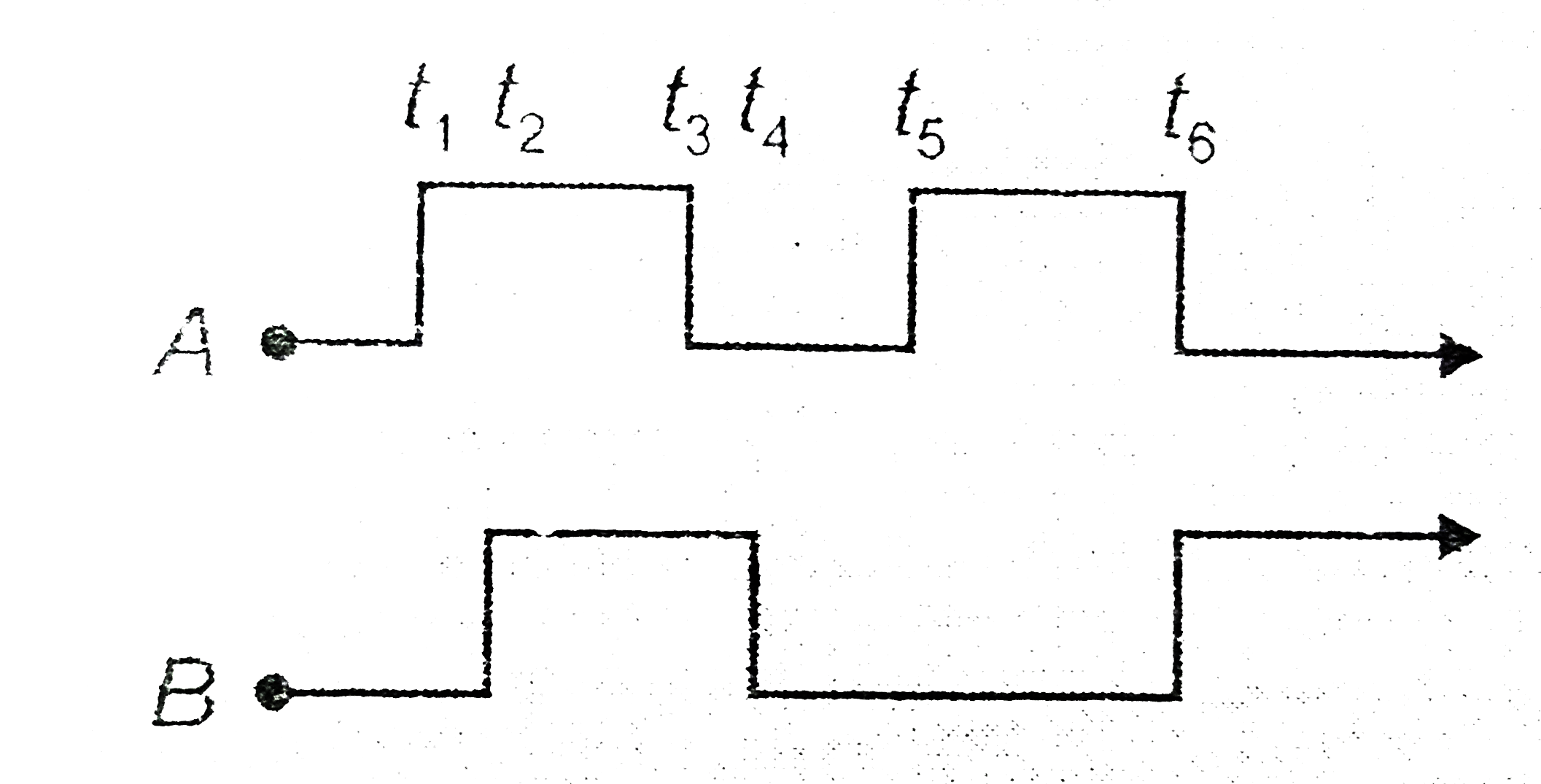
View SolutionShow the output waveform of OR gate for the following input waveforms of A and B
 View Solution
Show the output waveform of OR gate for the following input waveforms of A and B
 View Solution


