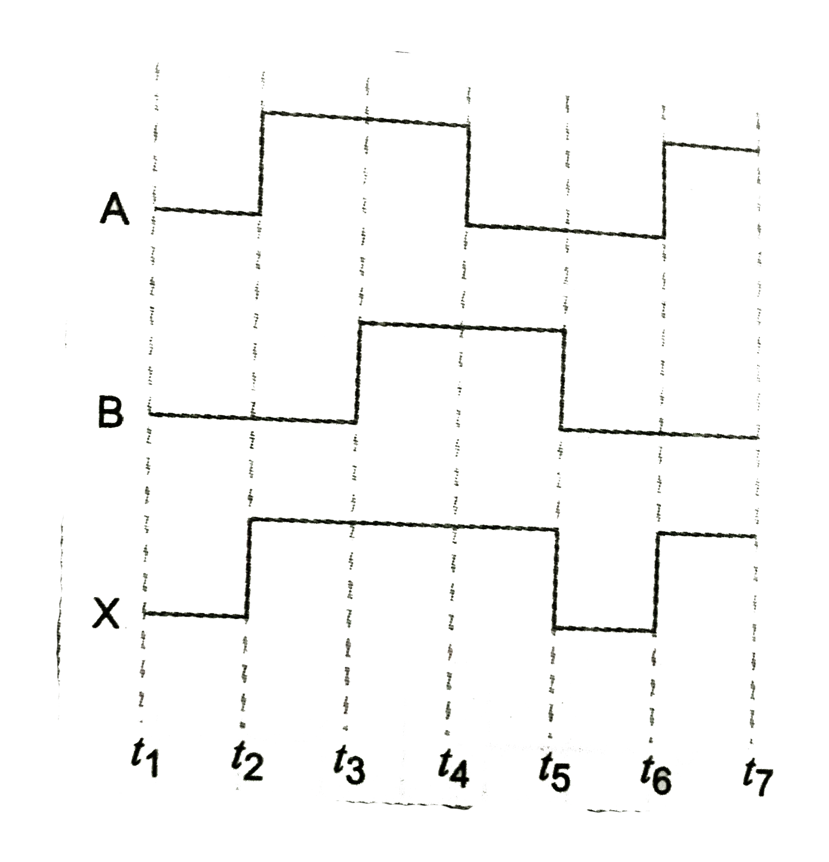
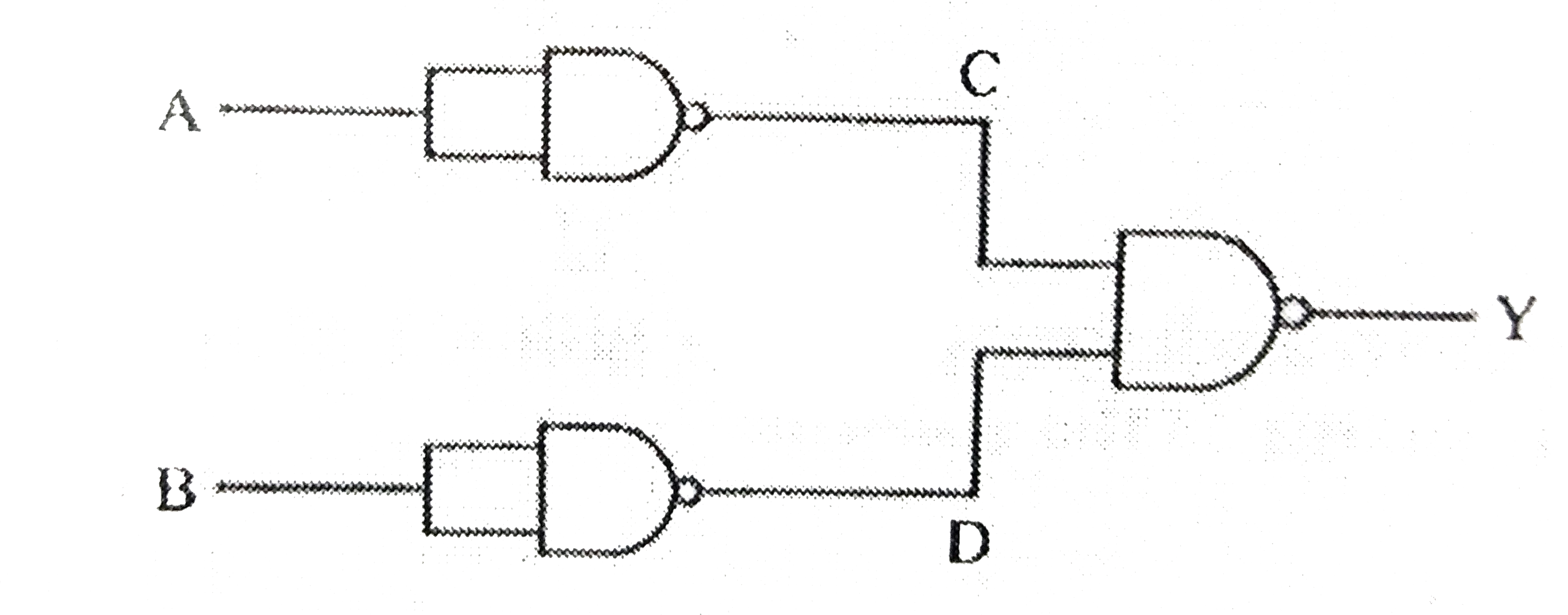
Drawn the output waveform at X, using thye given inputs A and B for the logic circuit shown in Fig. Also identify the logic operation performed by this circuit.

Video Solution
Text Solution
Output waveform at X, is shown in Fig.
The Boolean expression for the circuit is
y=¯¯¯¯¯¯¯¯¯¯¯A+B
and X=¯¯¯¯¯¯¯¯¯¯¯¯¯¯¯¯¯¯¯¯¯¯A+B=A+B

It means this logic circuit will work as OR gate.
|
Topper's Solved these Questions
- ELECTRONIC DEVICESBOOK - PRADEEPCHAPTER - ELECTRONIC DEVICESEXERCISE - SAMPLE PROBLEM
2 Videos
- ELECTRONIC DEVICESBOOK - PRADEEPCHAPTER - ELECTRONIC DEVICESEXERCISE - CONCEPTUAL PROBLEMS
1 Video
- ELECTROMAGNETIC WAVESBOOK - PRADEEPCHAPTER - ELECTROMAGNETIC WAVESEXERCISE - II Focus multiple choice question
5 Videos
- ELECTROSTATICSBOOK - PRADEEPCHAPTER - ELECTROSTATICSEXERCISE - ASSERTION-REASON TYPE QUESTIONS
2 Videos
Similar Questions
Draw the output waveformed at X, using the given inputs A and B for the logic circuit shows below. Also, identify the logic operation performed by this circuit.

View SolutionDraw the output waveform X, using the given inputs A and B for the logic circuit shows below. Also, identify the logic operation performed by this circuit.

View Solution
Knowledge Check
Identify the logic operation performed by the circuit as shown in the figure.
 AANDBORCNANDDNOT
The output Y of the logic circuit as shown in figure is
 A(A+B)⋅¯¯¯CB(A+C)⋅¯¯¯CC(B+C)⋅¯¯¯ADA+B+C
The output (X) of the logic circuit shown in figure will be
 AX=¯¯¯¯¯¯¯A.¯¯¯¯¯¯BBX=¯¯¯¯¯¯¯¯A.BCX=A.BDX=¯¯¯¯¯¯¯¯¯¯¯A+B
Identify the logic operation performed by the circuit given here.

View SolutionWrite the truth table for the logic circuit shown below and identify the logic operation performed by circuit.

View SolutionIdentify the logic operation carried out by the following circuit

View SolutionThe output (X) of the logic circuit shown in figure will be

View SolutionThe output (X) of the logic circuit shown in figure will be

View Solution
