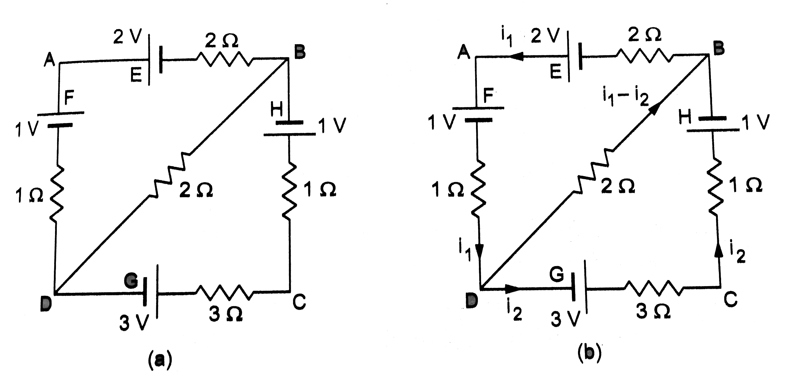
In the circuit shown in figure E,F, G and H are cell of emf 2,1,3, and 1V respectively. The resistances 2,1,3 and 1(Omega)are their respective internal resistance .Calculate (a)the potential difference between B and D and (b) the potential differences across the terminals of each of each of the cells G and H.
The correct Answer is:0.29V,3.143V,3.34V
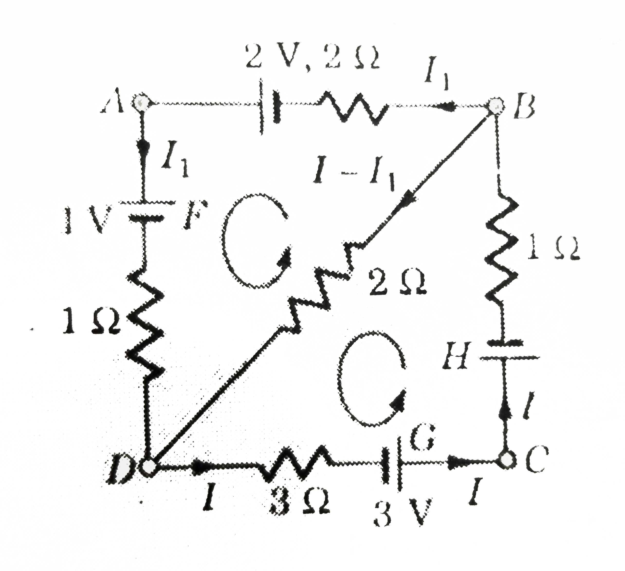
The distribution of current in the network following kircbboff's first rule has been
According to kirchbboff's second rule in the closed loop ABDA
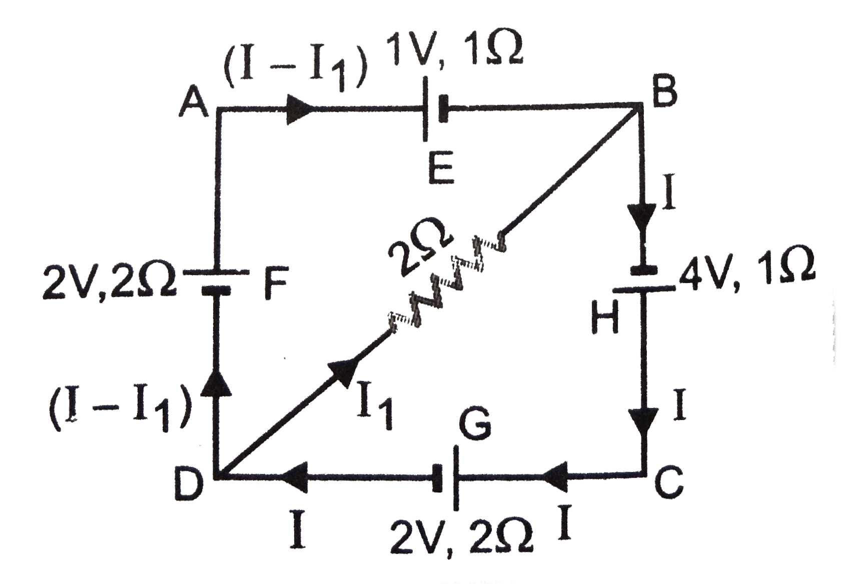
−1+2=1(I−I1)−2I1+(I−I1)2
or 1=3I−5I1 ....(i)
In the closed loop BCDB
4−2=1×l+2×I+2I1or2=3I+2I1.....(ii)
Subtricting (i) and (ii) we get
1=7l1orl1=17A
From (i) 1=3I−5×17
or 3I=1+57=127orl=127×3=47A
(i) Potential difference between D and B
=I1×2=17×2=27V=0.29V
(ii) potential difference across the terminals of G (receiving current for charging)
VC=ε+lr=2+47×2=22.(7)=3.143V
potential difference across the terminals of H
VH=ε'−lr'=4−47×1247=3.34V
Topper's Solved these Questions
- CURRENT ELECTRICITYBOOK - PRADEEPCHAPTER - CURRENT ELECTRICITYEXERCISE - Jee (main and advance)
4 Videos
- CURRENT ELECTRICITYBOOK - PRADEEPCHAPTER - CURRENT ELECTRICITYEXERCISE - Interger Type
2 Videos
- CURRENT ELECTRICITYBOOK - PRADEEPCHAPTER - CURRENT ELECTRICITYEXERCISE - Value based
2 Videos
- COMMUNICATION SYSTEMSBOOK - PRADEEPCHAPTER - COMMUNICATION SYSTEMSEXERCISE - MODEL TEST PAPER-2
9 Videos
- DUAL NATURE OF RADIATION AND MATTERBOOK - PRADEEPCHAPTER - DUAL NATURE OF RADIATION AND MATTEREXERCISE - Exercise
191 Videos
Similar Questions
In the circuit shown in E, F, G, and H are cells of emf 2,1,3 and 1 V, respectively. The resistances 2Ω,1Ω,3Ωand1Ω are their respectivle internal resistances.

i. Find the potential difference between B and D.
(ii) Calculate the potential differences across the terminals of each of the cells G and H.
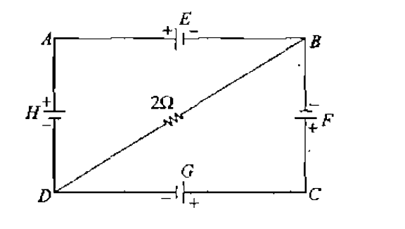
View SolutionIn the circuit shown in figure-3.159 cells E,F,G and H are of EMF 2V, 1V,3V and 1V respevitly and their internal resitance are 2Ω,1Ω,3Ω and 1Ω respectively Calculate
(a) The potential difference between points B and D
(d) The potential difference across the terminals of the cell G and H.
View Solution
Knowledge Check
In the circuit shown E,F,G and H are cells of emf 2V,1V,3V and 1V respectively and their internal resistance are 2Ω,1Ω,3Ω and 1Ω respectively.
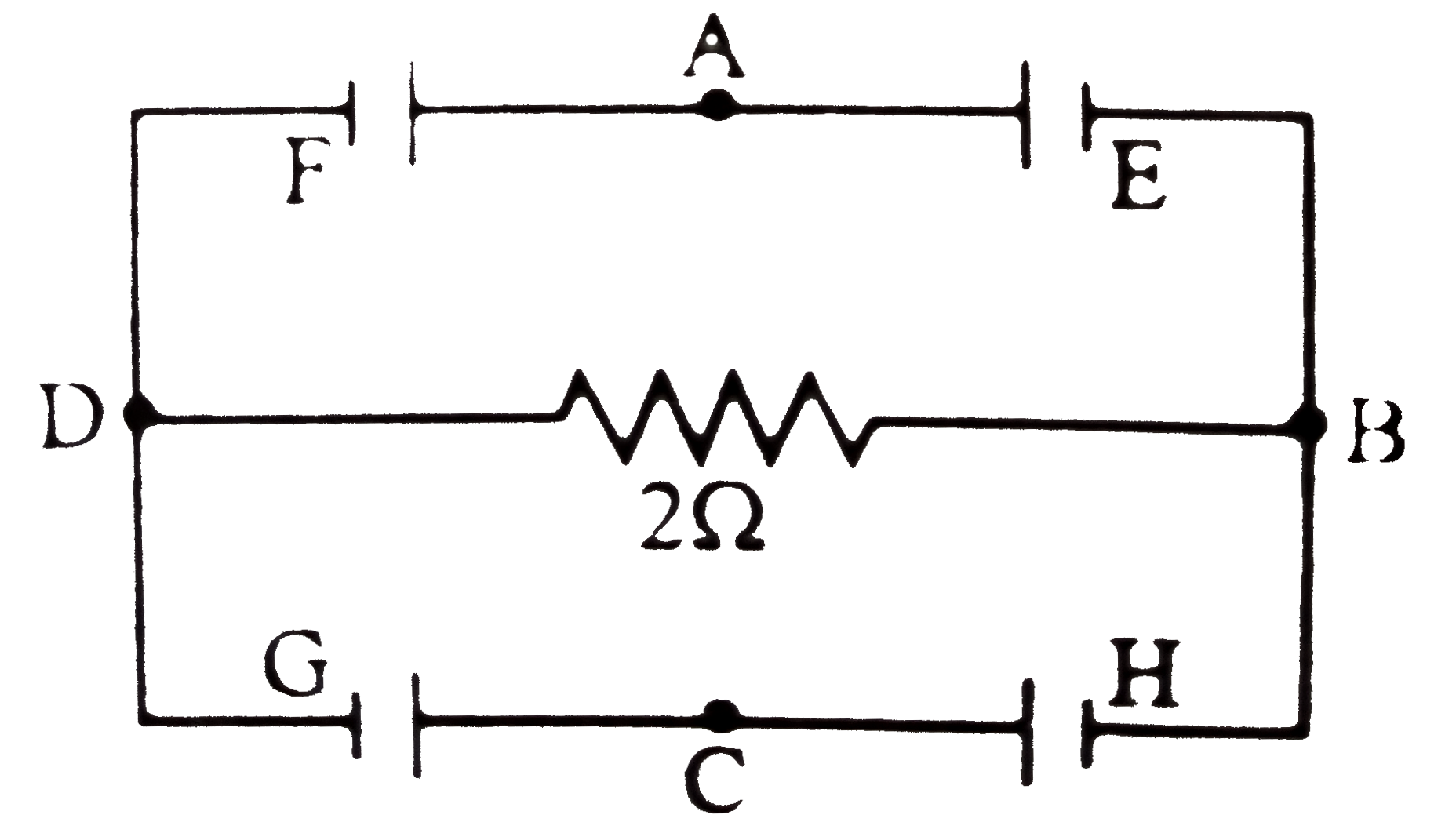 AVD−VB=−2/13VBVD−VB=2/13VCVG=21/13V=potential difference across GDVH=19/13V=potential difference across H
In the circuit E,F,G,Hare cell of emf 2,1,3and 1Ω respectively .The potential difference across the terminal of each of the cell G and H are
 A1.46V,1.61VB1.61V,1.46VC2.52V,1.61VD1.61V,2.25V
Two cells A and B of e.m.f.2 V and 1.5 V respectively, are connected as shown in figure through an external resistance 10 Ω The internal resistance of each cell is 5 Ω. The potential difference EAandEB across the terminals of the cells A and B respectively are
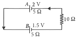 AEA=2.0v,EB=1.5VBEA=2.125V,EB=1.375VCEA=1.875V,EB=1.625VDEA=1.875V,EB=1.375V
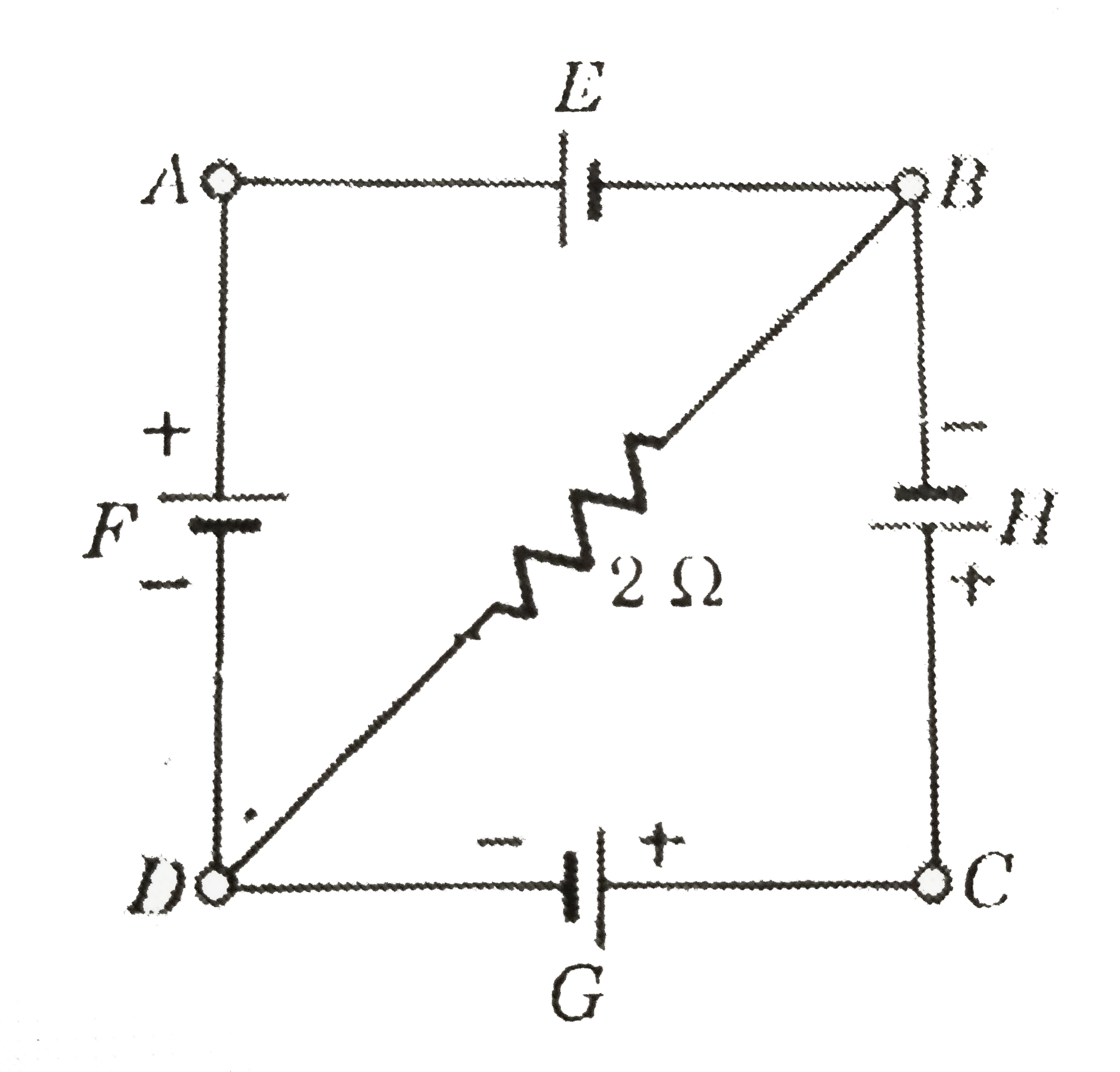
In the circuit shown in figure. The cells E,F,G and H have e.m.f's 2,1,3 and 1 V and internal resistance 2,1,3 and 1Ω respectively. Find the potential differences between points B and D, and across the terminals of the cells G and H.
View SolutionTwo non-ideal batteries have e.m.f 2V and 8V respectively and internal resistance 1 Omega and 2 Omega respectively as shown in the figure. If the potential difference between a and b is zero then the resistance R has a value
_PHY_E01_014_Q01.png)
View SolutionA cell of emf 'E' is connected across a resistance R.The potential difference between the terminals of the cell is found to be "V" .The internal resistance of the cell must be:
View Solutionv31
View SolutionA cell of e.mf. E and internal resistance r is connected in series with an external resistance nr. Then, the ratio of the terminal potential difference to E.M.F.is
View Solution
