A narrow stream of electrons with kinetic enrgy T=10keV passes through a polycrystalline aluminium foil, forming a system of diffraction fringes on a screen. Calculate tha interplanar distacne corresponding to the reflection of third order from a certain system of crystal planes if it is responsible for a diffraction ring of diameter D=3.20cm. The distacnce between the foil and the screen is l=10.0cm.
See the analogous problem with X- rays (5.156)
The glancing angle is obtained from
tan2θ=D2l
where D= diameter of the ring, l= distance from the foil to the screen. Then for the third order Bragg reflection
2dsinθ=kλ=k2πħ√2mT,(k=3)
Thus d=πħk√2mTsinθ=0.232nm
Topper's Solved these Questions
- ATOMIC AND NUCLEAR PHYSICSBOOK - IE IRODOV, LA SENA & SS KROTOVCHAPTER - ATOMIC AND NUCLEAR PHYSICSEXERCISE - Properties Of Atom
69 Videos
- ATOMIC AND NUCLEAR PHYSICSBOOK - IE IRODOV, LA SENA & SS KROTOVCHAPTER - ATOMIC AND NUCLEAR PHYSICSEXERCISE - Molecules And Crystals
48 Videos
- ATOMIC AND NUCLEAR PHYSICSBOOK - IE IRODOV, LA SENA & SS KROTOVCHAPTER - ATOMIC AND NUCLEAR PHYSICSEXERCISE - Elementary Particles
20 Videos
- DIRECT CURRENTBOOK - IE IRODOV, LA SENA & SS KROTOVCHAPTER - DIRECT CURRENTEXERCISE - All Questions
15 Videos
Similar Questions
On transmitting a bem of Xrays with wavelength λ=17.8± through a polycrystalline specimen a system of diffraction rings is produced on a screen located at a distance l=45 cm fom the specimen. Determine the radius of the bright rind corresponding to second order of reflection from the system of planes with interplanar distance d=155±
View SolutionA narrow stream of vanadium atoms in the ground state .4F3/2 is passed through a transverse strongly inhomogeneous magnetic field of lengthl1=5.0cm as in the Stern-Gerlach experiment. The beam splitting is observed on a screen located at a distance l2=15cm from the magnet. The kinetic energy of the atoms is T=22meV. At what value of the gradient of the magnetic field induction B is the distance between the extreme components of the split beam in the screen equal to δ=2.0mm ?
View Solution
Knowledge Check
Wave property of electrons implies that they will show diffraction effects. Davission and Germer demonstrated this by diffracting electrons from crystals. The law governing the diffraction from a crystal is obtained by requiring that electron waves reflected from the planes of atoms in a crystal interfere constructively (see figure)

In an experiment, electrons are made to pass through a narrow slit of width 'd' comparable to either de-Broglie wavelength. They are detected on a screen at a distance 'D' from the slit

The following graphs that can be expected to represent the number of electrons 'N' detected as a function of the detector position 'y' (y=0 corresponds to the middle of the slit) isA B
B C
C D
D
Following experiment was performed by J.J. Thomson in order to measure ratio of charge e and mass m of electron.
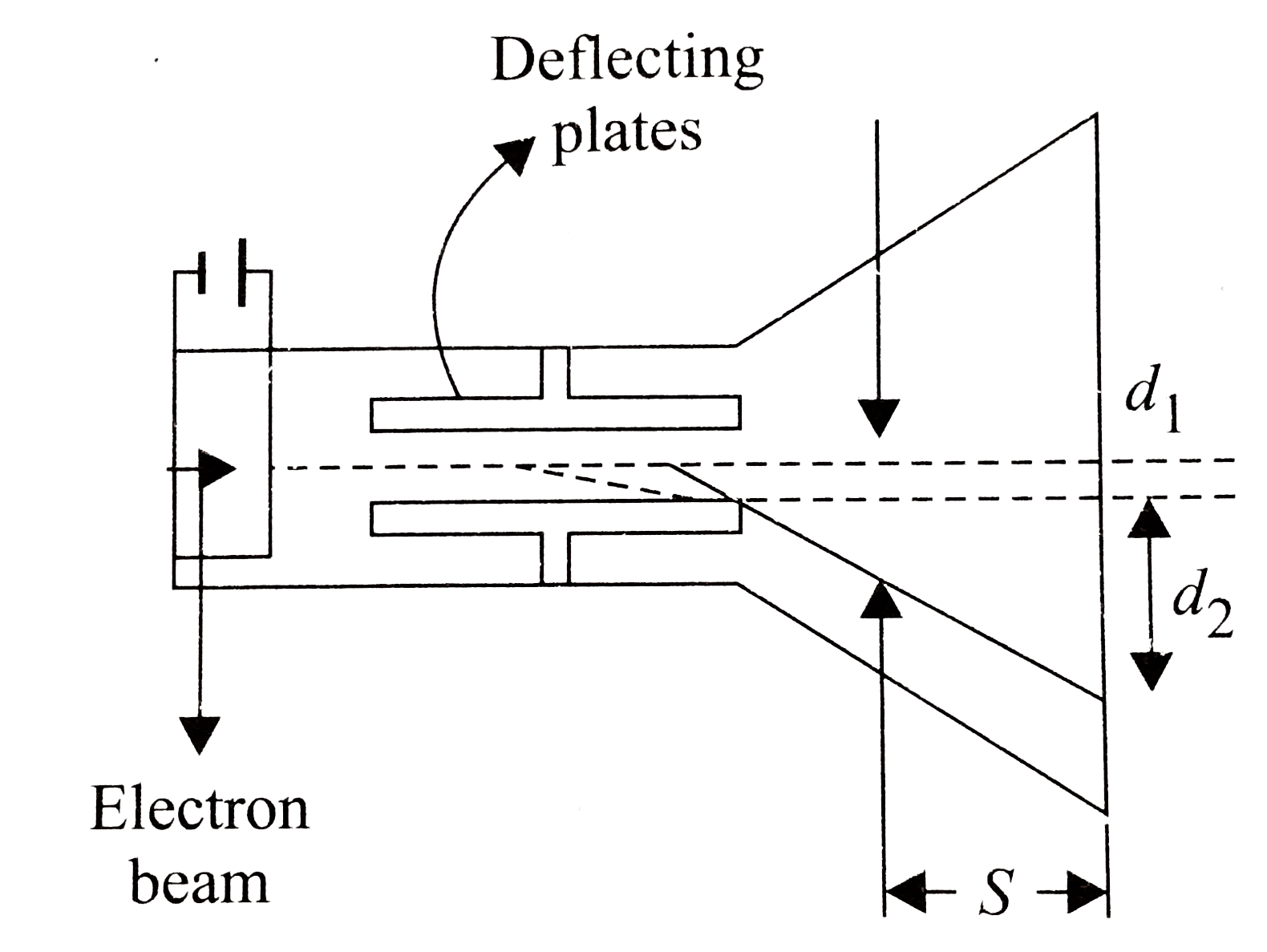
Electrons emitted from a hot filament are accelerated by a potential difference V. As the electrons pass through deflecting plates, they encounter both electric and magnetic fields. the entire region in which electrons leave the plates they enters a field free region that extends to fluorescent screen. The entire region in which electrons travel is evacuated.
Firstly, electric and magnetic fields were made zero and position of undeflected electron beam on the screen was noted. The electric field was turned on and resulting deflection was noted. Deflection is given by d1=eEL22mV2 where L = length of deflecting plate and v = speed of electron.
In second part of experiment, magnetic field was adjusted so as to exactly cancel the electric force leaving the electron beam undeflected. This gives eE=evB. Using expression for d1 we can find out em=2d1EB2L2
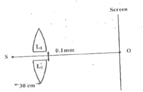
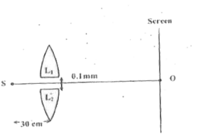
A beam of electron with velocity 3×10⁷ms−1 is deflected 2 mm while passing through 10 cm in an electric field of 1800V/m perpendicular to its path. e/m for electron isA1.5×1011Ckg−1B2×1011Ckg−1C2.5×1011Ckg−1D3×1011Ckg−1Two independent light sources are always incoherent. This is because phase of light emitted is random and phase difference, at any point, changes very rapidly with time. So as to obtain observable interference, we require coherent sources which emit light of same wavelength such that phase difference at any point does not change with time. In different interference experiments, the method to obtain two coherent sources could be different. In Fresnel's biprism experiment, two virtual images of a real source, which are formed due to refraction at the biprism, act as coherent source. In Lloyd’s mirror experiment, a real source and its virtual image formed due to reflection at a plane mirror act as coherent source. Two images of a source or a source and its image are coherent because of their phase correlation. It is also possible to obtain coherent sources by forming two images of a point source in the following manner.As shown in the figure, S is a monochromatic point source. A thin circular lens is cut into two identical halves L, and L2 by a plane passing through a diameter. L1 is kept above the axis and L2 below it is in a symmetrical manner such that the gap between the two is 0.1 mm. Each forms an image Qf the source and the two images, say, Si and S2 , act as coherent sources. Superposition of waves from these coherent sources will result in observable interference and a pattern can be obtained on a screen.The lens which has been cut to from L, and L2 is made of a material of refractive index 1.5 for the wavelength emitted by the source S. Radius of curvature of each surface of the lens is 18 cm. Source S is 30 cm along the axis fro Li and L2 . It is found that smallest distance from O along the screen at which intensity is half of the maximum intensity is 0.1 mm. It is also observed that the highest order of maximum intensity in the interference patter is 416.
Q Phase difference between the light waves 0.1 mm from along the screen, where intensity is half the maximum value, is
 A) tt/2Bk/3Ctt/4Dir/6
A parallel stream of monoenergetic electrons falls normally on a diaphragm with narrow square slit of width b=1.0μm. Find the velocity of the electrons if the width of the central diffraction maximum formed on a screen located at a distance l=50cm from the slit is equal to Δx=0.36mm.
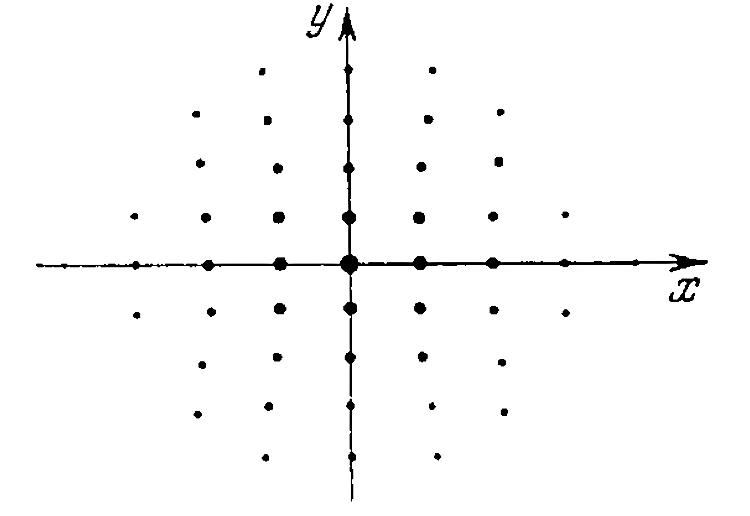
View SolutionA beam of X-rays with wavelength λ=40± falls normally on aplne rectangular array of scattering centres and produces a system of diffraction maxima (Fig.) on a plane screen removed from the array by a distance l=10cm. Find the array periods a and b along the x and y axes if the distance between symmetrically located maxima of second order are equal to Δx=60mm (along the x axis) and Δy=40mm (along the yaxis).
View SolutionFollowing experiment was performed by J.J. Thomson in order to measure ratio of charge e and mass m of electron.

Electrons emitted from a hot filament are accelerated by a potential difference V. As the electrons pass through deflecting plates, they encounter both electric and magnetic fields. the entire region in which electrons leave the plates they enters a field free region that extends to fluorescent screen. The entire region in which electrons travel is evacuated.
Firstly, electric and magnetic fields were made zero and position of undeflected electron beam on the screen was noted. The electric field was turned on and resulting deflection was noted. Deflection is given by d1=eEL22mV2 where L = length of deflecting plate and v = speed of electron.
In second part of experiment, magnetic field was adjusted so as to exactly cancel the electric force leaving the electron beam undeflected. This gives eE=evB. Using expression for d1 we can find out em=2d1EB2L2
A beam of electron with velocity 3×10⁷ms−1 is deflected 2 mm while passing through 10 cm in an electric field of 1800V/m perpendicular to its path. e/m for electron is
View SolutionTwo independent light sources are always incoherent. This is because phase of light emitted is random and phase difference, at any point, changes very rapidly with time. So as to obtain observable interference, we require coherent sources which emit light of same wavelength such that phase difference at any point does not change with time. In different interference experiments, the method to obtain two coherent sources could be different. In Fresnel's biprism experiment, two virtual images of a real source, which are formed due to refraction at the biprism, act as coherent source. In Lloyd’s mirror experiment, a real source and its virtual image formed due to reflection at a plane mirror act as coherent source. Two images of a source or a source and its image are coherent because of their phase correlation. It is also possible to obtain coherent sources by forming two images of a point source in the following manner.As shown in the figure, S is a monochromatic point source. A thin circular lens is cut into two identical halves L, and L2 by a plane passing through a diameter. L1 is kept above the axis and L2 below it is in a symmetrical manner such that the gap between the two is 0.1 mm. Each forms an image Qf the source and the two images, say, Si and S2 , act as coherent sources. Superposition of waves from these coherent sources will result in observable interference and a pattern can be obtained on a screen.The lens which has been cut to from L, and L2 is made of a material of refractive index 1.5 for the wavelength emitted by the source S. Radius of curvature of each surface of the lens is 18 cm. Source S is 30 cm along the axis fro Li and L2 . It is found that smallest distance from O along the screen at which intensity is half of the maximum intensity is 0.1 mm. It is also observed that the highest order of maximum intensity in the interference patter is 416.
Q Distance of a point from O, at which the sixth order minimum is formed, will be
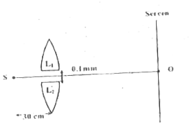
View SolutionTwo independent light sources are always incoherent. This is because phase of light emitted is random and phase difference, at any point, changes very rapidly with time. So as to obtain observable interference, we require coherent sources which emit light of same wavelength such that phase difference at any point does not change with time. In different interference experiments, the method to obtain two coherent sources could be different. In Fresnel's biprism experiment, two virtual images of a real source, which are formed due to refraction at the biprism, act as coherent source. In Lloyd’s mirror experiment, a real source and its virtual image formed due to reflection at a plane mirror act as coherent source. Two images of a source or a source and its image are coherent because of their phase correlation. It is also possible to obtain coherent sources by forming two images of a point source in the following manner.As shown in the figure, S is a monochromatic point source. A thin circular lens is cut into two identical halves L, and L2 by a plane passing through a diameter. L1 is kept above the axis and L2 below it is in a symmetrical manner such that the gap between the two is 0.1 mm. Each forms an image Qf the source and the two images, say, Si and S2 , act as coherent sources. Superposition of waves from these coherent sources will result in observable interference and a pattern can be obtained on a screen.The lens which has been cut to from L, and L2 is made of a material of refractive index 1.5 for the wavelength emitted by the source S. Radius of curvature of each surface of the lens is 18 cm. Source S is 30 cm along the axis fro Li and L2 . It is found that smallest distance from O along the screen at which intensity is half of the maximum intensity is 0.1 mm. It is also observed that the highest order of maximum intensity in the interference patter is 416.
Q Fringe width is nearly
View Solution
