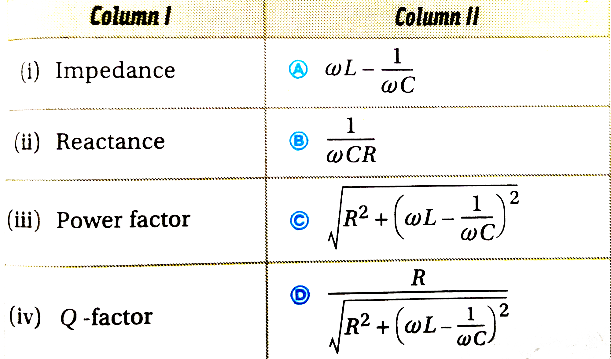
A series combination of an inductor of self-inductance L, capacitor of capacitance C and resistor R is connected to an alternating voltage source of V=V0sinωt. The current through the circuit is I=I0sin(ωt−θ),where I0=V0√R2+(ω−1ωC)2andθ=tan−11R(ωL−1ωC).
Now that, the frequency of both voltage and current is f=ω2π . The rms value of these parameters during one complete cycles are Vrms=V0√2andIrms=I0√2 respectively. These values are shown in alternating voltmeter and ammeter.
The power consumed by the circuit P=VI. The mean value i.e., the effective power of the circuit in a complete cycle is ¯¯¯P=VrmsIrmscosθ. This cosθ is termed the power factor.
Which element is responsible for the power consumption in an alternating current circuit?Solution in Bengali
only resistor
only inductor
only capacitor
resistor,inductor and capacior
The correct Answer is:A
Step by step video, text & image solution for A series combination of an inductor of self-inductance L, capacitor of capacitance C and resistor R is connected to an alternating voltage source of V=V_0sinomegat. The current through the circuit is I=I_0sin(omegat-theta),where I_0=V_0/(sqrt(R^2+(omega-1/(omegaC))^2))andtheta=tan^-1 ""1/R(omegaL-1/(omegaC)). Now that, the frequency of both voltage and current is f=omega/(2pi) . The rms value of these parameters during one complete cycles are V_(rms)=V_0/sqrt2andI_(rms)=I_0/sqrt2 respectively. These values are shown in alternating voltmeter and ammeter. The power consumed by the circuit P=VI. The mean value i.e., the effective power of the circuit in a complete cycle is overlineP=V_(rms)I_(rms)costheta. This costheta is termed the power factor. Which element is responsible for the power consumption in an alternating current circuit? by Physics experts to help you in doubts & scoring excellent marks in Class 12 exams.
Updated on:21/07/2023Topper's Solved these Questions
- ALTERNATING CURRENT BOOK - CHHAYA PUBLICATIONCHAPTER - ALTERNATING CURRENT EXERCISE - ENTRANCE CORNER (Integer Answer Type)
8 Videos
- ALTERNATING CURRENT BOOK - CHHAYA PUBLICATIONCHAPTER - ALTERNATING CURRENT EXERCISE - EXAMINATION ARCHIVE WITH SOLUTIONS (WBCHSE)
20 Videos
- ALTERNATING CURRENT BOOK - CHHAYA PUBLICATIONCHAPTER - ALTERNATING CURRENT EXERCISE - ENTRANCE CORNER (Matrix match type)
5 Videos
- BOOK - CHHAYA PUBLICATIONCHAPTER - EXERCISE - EXAMPLE
1 Videos
- ATOMBOOK - CHHAYA PUBLICATIONCHAPTER - ATOMEXERCISE - CBSE SCANNER
18 Videos
Similar Questions
A resistance and a capacitor is connected in series with an alternating voltage of rms value 13 V. The terminal voltage of the resistor is 12V and that across the capacitor is (n+0.38)V. What is the value of n?
View SolutionAn ac having a peak value 1.41 A is used to heat a wire. A dc producing the same heating rate will be approximately
View SolutionMatch the columns for a series LCR circuit.

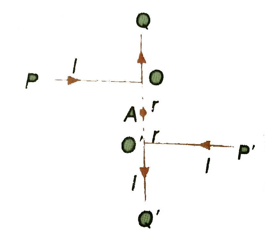
View SolutionThrough each of the two wires POQ and P'O'Q and electric current I is passing [Fig. 1.23]. The points Q,O,O and Q' are collinear. Determine the magnetic field at the midpoint A of OO'.

View SolutionUsing de Broglie's hypothesis , explain with the help of a suitable diagram , Bohr's second postulate of quantisation of energy levels in a hydrogen atom.
View SolutionAn AC voltage source V=V_0siomegat is connected across resistance R and capacitance C as shown in figureure. It is given that R=1/omegaC . The peak current is I_0 . If the angular frequency of the voltage source is changed to omega/sqrt3, then the new peak current in the circuit is .
View Solutionप्रत्यावर्ती वोल्टेज स्त्रोत V=V0sinωt से प्रेरकत्व L , धारिता C तथा प्रतिरोध R तीनो श्रेणीक्रम में जुड़े है सिद्ध कीजिए कि परिपथ कि प्रतिबाधा Z=√R2+(ωL−1ωC)2 तथा tanϕ=ωL−1ωCR जहाँ ϕ धारा तथा वोल्टेज के बीच कालान्तर है ।
View Solutionप्रत्यावर्ती वोल्टेज-स्रोत V=V0sinωt से प्रेरकत्व L, धारिता C तथा प्रतिरोध R तीनों श्रेणीक्रम में जुड़े हैं। सिद्ध कीजिए कि परिपथ की प्रतिबाधा Z का मान :
Z=√R2(ωL−1ωC)2 तथा tanϕ=ωL−1ωCR
जहाँ धारा तथा वोल्टेज के बीच कलान्तर है ।
View SolutionA series combination of an inductor of self-inductance L, capacitor of capacitance C and resistor R is connected to an alternating voltage source of V=V0sinωt. The current through the circuit is I=I0sin(ωt−θ),where I0=V0√R2+(ω−1ωC)2andθ=tan−11R(ωL−1ωC).
Now that, the frequency of both voltage and current is f=ω2π . The rms value of these parameters during one complete cycles are Vrms=V0√2andIrms=I0√2 respectively. These values are shown in alternating voltmeter and ammeter.
The power consumed by the circuit P=VI. The mean value i.e., the effective power of the circuit in a complete cycle is ¯¯¯P=VrmsIrmscosθ. This cosθ is termed the power factor.
V=V0sinωt electromotive force is applied to an alternating circuit consisting of resistance R' and an inductor of self-inductance L. The phase difference between the voltage and current is
View SolutionA series combination of an inductor of self-inductance L, capacitor of capacitance C and resistor R is connected to an alternating voltage source of V=V_0sinomegat . The current through the circuit is I=I_0sin(omegat-theta) ,where I_0=V_0/(sqrt(R^2+(omega-1/(omegaC))^2)) and theta=tan^-1 ""1/R(omegaL-1/(omegaC)) . Now that, the frequency of both voltage and current is f=omega/(2pi) . The rms value of these parameters during one complete cycles are V_(rms)=V_0/sqrt2 and I_(rms)=I_0/sqrt2 respectively. These values are shown in alternating voltmeter and ammeter. The power consumed by the circuit P=VI. The mean value i.e., the effective power of the circuit in a complete cycle is overlineP=V_(rms)I_(rms)costheta . This costheta is termed the power factor. the power factor of the circuit is question (i) is
View SolutionA series combination of an inductor of self-inductance L, capacitor of capacitance C and resistor R is connected to an alternating voltage source of V=V0sinωt. The current through the circuit is I=I0sin(ωt−θ),where I0=V0√R2+(ω−1ωC)2andθ=tan−11R(ωL−1ωC).
Now that, the frequency of both voltage and current is f=ω2π . The rms value of these parameters during one complete cycles are Vrms=V0√2andIrms=I0√2 respectively. These values are shown in alternating voltmeter and ammeter.
The power consumed by the circuit P=VI. The mean value i.e., the effective power of the circuit in a complete cycle is ¯¯¯P=VrmsIrmscosθ. This cosθ is termed the power factor.
In the circuit in question (i) the inductor is replaced by a pure capacitor, the phase difference between the current and terminal voltage of the capacitor is
View SolutionA series combination of an inductor of self-inductance L, capacitor of capacitance C and resistor R is connected to an alternating voltage source of V=V0sinωt. The current through the circuit is I=I0sin(ωt−θ),where I0=V0√R2+(ω−1ωC)2andθ=tan−11R(ωL−1ωC).
Now that, the frequency of both voltage and current is f=ω2π . The rms value of these parameters during one complete cycles are Vrms=V0√2andIrms=I0√2 respectively. These values are shown in alternating voltmeter and ammeter.
The power consumed by the circuit P=VI. The mean value i.e., the effective power of the circuit in a complete cycle is ¯¯¯P=VrmsIrmscosθ. This cosθ is termed the power factor.
The power factor of the circuit in question (iii) is
View SolutionA series combination of an inductor of self-inductance L, capacitor of capacitance C and resistor R is connected to an alternating voltage source of V=V0sinωt. The current through the circuit is I=I0sin(ωt−θ),where I0=V0√R2+(ω−1ωC)2andθ=tan−11R(ωL−1ωC).
Now that, the frequency of both voltage and current is f=ω2π . The rms value of these parameters during one complete cycles are Vrms=V0√2andIrms=I0√2 respectively. These values are shown in alternating voltmeter and ammeter.
The power consumed by the circuit P=VI. The mean value i.e., the effective power of the circuit in a complete cycle is ¯¯¯P=VrmsIrmscosθ. This cosθ is termed the power factor.
The voltage applied in an LCR circuit having R=10Ω,L=10mHand C=1μFis V=20sinωt volt. For what frequency of the applied voltage will the current reach its peak value?
View SolutionA series combination of an inductor of self-inductance L, capacitor of capacitance C and resistor R is connected to an alternating voltage source of V=V0sinωt. The current through the circuit is I=I0sin(ωt−θ),where I0=V0√R2+(ω−1ωC)2andθ=tan−11R(ωL−1ωC).
Now that, the frequency of both voltage and current is f=ω2π . The rms value of these parameters during one complete cycles are Vrms=V0√2andIrms=I0√2 respectively. These values are shown in alternating voltmeter and ammeter.
The power consumed by the circuit P=VI. The mean value i.e., the effective power of the circuit in a complete cycle is ¯¯¯P=VrmsIrmscosθ. This cosθ is termed the power factor.
The phase difference between the voltage and peak current in question (v) is
View SolutionA series combination of an inductor of self-inductance L, capacitor of capacitance C and resistor R is connected to an alternating voltage source of V=V_0sinomegat . The current through the circuit is I=I_0sin(omegat-theta) ,where I_0=V_0/(sqrt(R^2+(omega-1/(omegaC))^2)) and theta=tan^-1 ""1/R(omegaL-1/(omegaC)) . Now that, the frequency of both voltage and current is f=omega/(2pi) . The rms value of these parameters during one complete cycles are V_(rms)=V_0/sqrt2 and I_(rms)=I_0/sqrt2 respectively. These values are shown in alternating voltmeter and ammeter. The power consumed by the circuit P=VI. The mean value i.e., the effective power of the circuit in a complete cycle is overlineP=V_(rms)I_(rms)costheta . This costheta is termed the power factor. The frequency of the applied alternating voltage in an ac circuit is 50 Hz.Resistance and self inductance are 37.6Omega and 120 mH . The phase difference between the voltage and current is
View Solution
