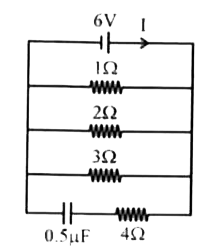
In the given circuit diagram, in the steady state the current through the battery and the charge on the capacitor respectively are
A
2 A and 3μC
B
11 A and 3μC
C
611Aand127μC
D
zero ampere and 3μF
Video Solution
Text Solution
The correct Answer is:B
The resistances 1Ω,2Ω,3Ω are in parallel
∴1R=11+12+13=116 ∴R=611Ω
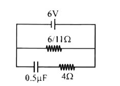
In the steady state, the capacitor is fully charged and no current flows through it.
∴No current flows through the 4Ω resistance
∴1=ER=6611=11A
and Q=CV=0.5×10−6×6=3×10−6=3μC
|
Topper's Solved these Questions
- ELECTROSTATICSBOOK - MARVEL PUBLICATIONCHAPTER - ELECTROSTATICSEXERCISE - TEST YOUR GRASP
20 Videos
- ELECTRONS AND PHOTONS BOOK - MARVEL PUBLICATIONCHAPTER - ELECTRONS AND PHOTONS EXERCISE - TEST YOUR GRASP - 17
15 Videos
- GRAVITATION BOOK - MARVEL PUBLICATIONCHAPTER - GRAVITATION EXERCISE - TEST YOUR GRASP -2
20 Videos
Similar Questions
Knowledge Check
In the given circuit

the current through the battery isA0.5 AB1AC1.5 AD2AIn the given circuit,
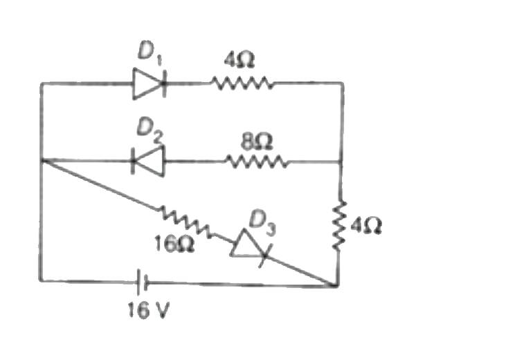
the current through the battery isA1.5 AB2AC3AD5.33AIn the given circuit
The current through the battery is
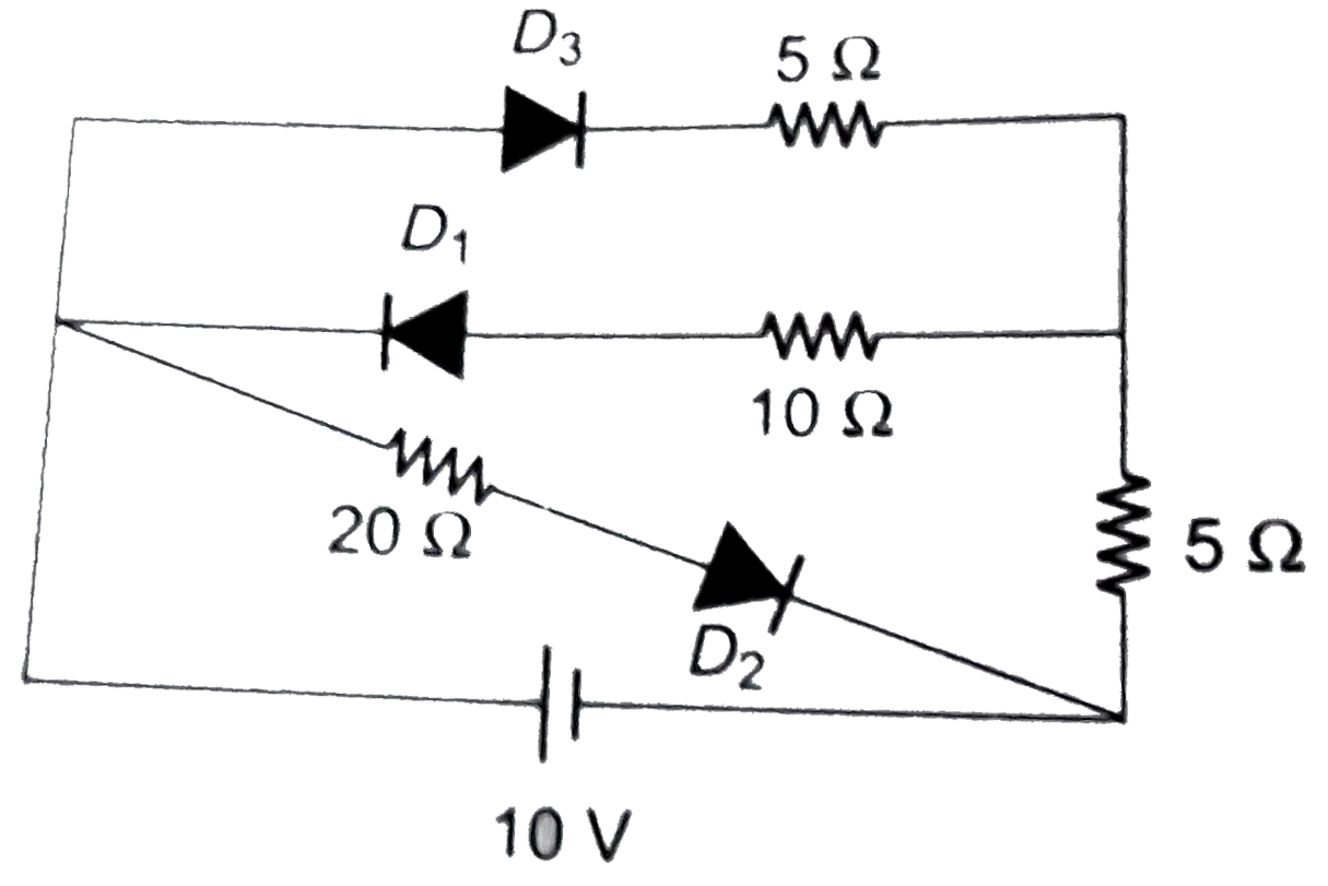 A0.5AB1AC1.5AD2A
In the given circuit diagram when the current reaches steady state in the circuit , the charge on the capacitor of capacitance C will be :
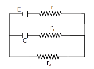
View Solution
In the given circuit diagram when the current reaches steady stte in the circuit, the charge on the capacitor of capacitance C will be:-
View SolutionIn the given circuit for ideal diode, the current through the battery is

View SolutionIn the circuit shown in the figure, in steady state:

The current drawn from the battery is
View SolutionIn the given circuit,
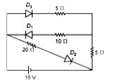
The current through battery is
View Solution

