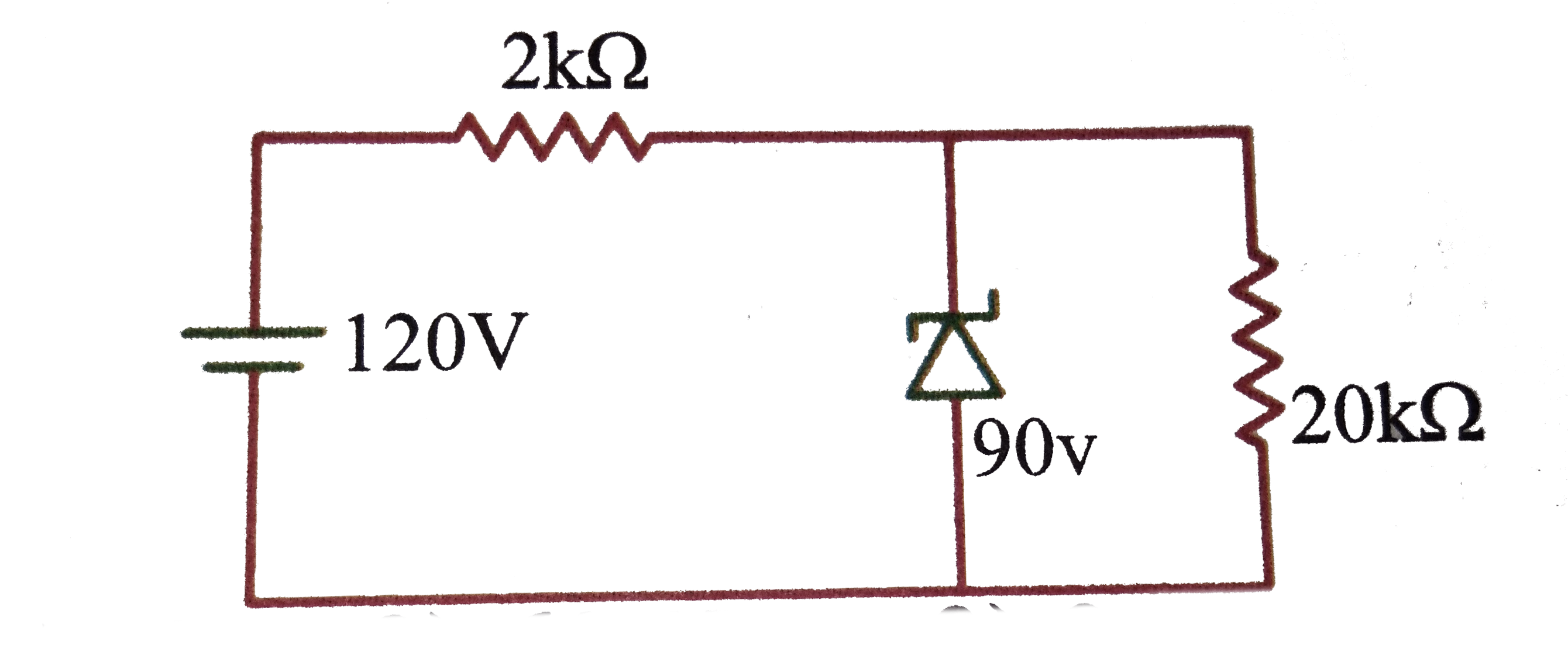
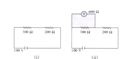
In the figure shown the potential drop across the series resistor is
A
30 V
B
60 V
C
90 V
D
120 V
Video Solution
Text Solution
The correct Answer is:A
.
|
Topper's Solved these Questions
- SEMI CONDUCTOR DEVICESBOOK - NARAYNACHAPTER - SEMI CONDUCTOR DEVICESEXERCISE - Level-I (H.W)
26 Videos
- RAY OPTICS AND OPTICAL INSTRAUMENTS BOOK - NARAYNACHAPTER - RAY OPTICS AND OPTICAL INSTRAUMENTS EXERCISE - EXERCISE- 4 One or more than one correct answer type
13 Videos
- SEMICONDUCTOR ELECTRONICSBOOK - NARAYNACHAPTER - SEMICONDUCTOR ELECTRONICSEXERCISE - ADDITIONAL EXERCISE (ASSERTION AND REASON TYPE QUESTIONS :)
19 Videos
Similar Questions
Knowledge Check
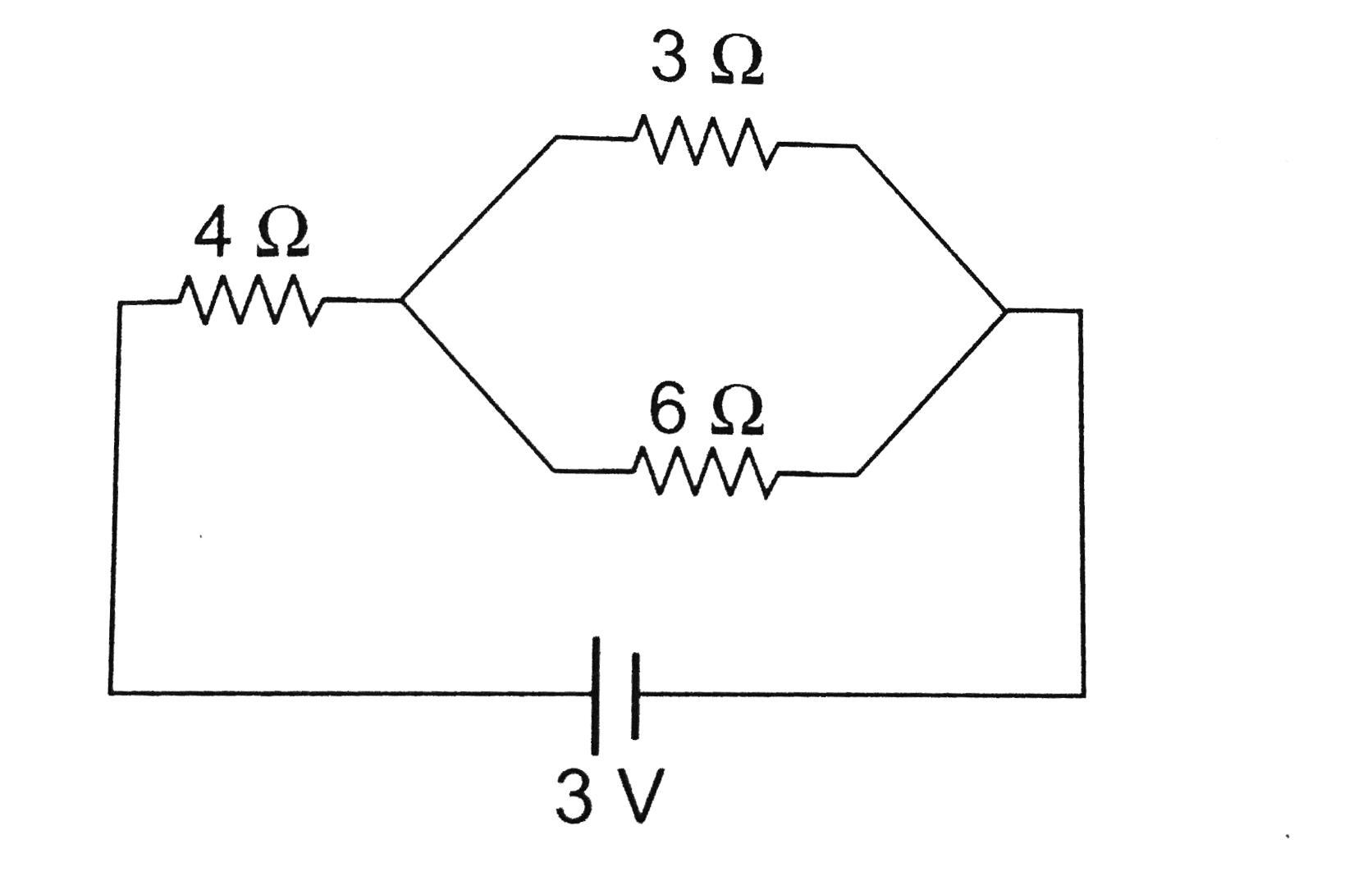
The potential drop across the 3Ω resistor is
 A1VB1.5VC2VD3V
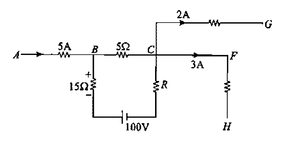
In the circuit shown, the voltage drop across the 15Ω resistor is 30V having the polarity as indicated. The ratio of potential difference across 5Ω resistor and resistance R is :
 A2/7B0.4C5/7D1
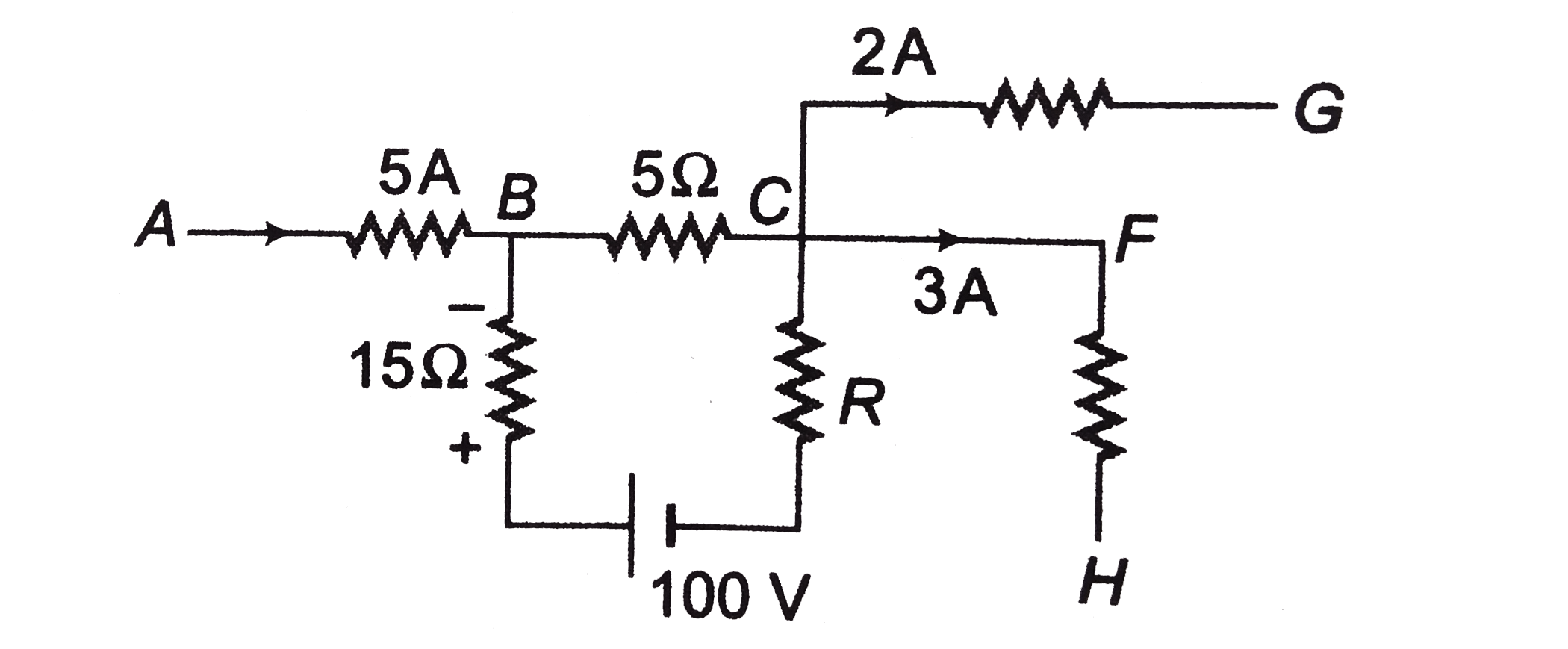
In the circuit shown the voltage drop across the 15Ω resistor is 30V having the polarity as indicated. The ratio of potential difference across 5Ω and resistance R is
 A2/7B0.4C5/7D1
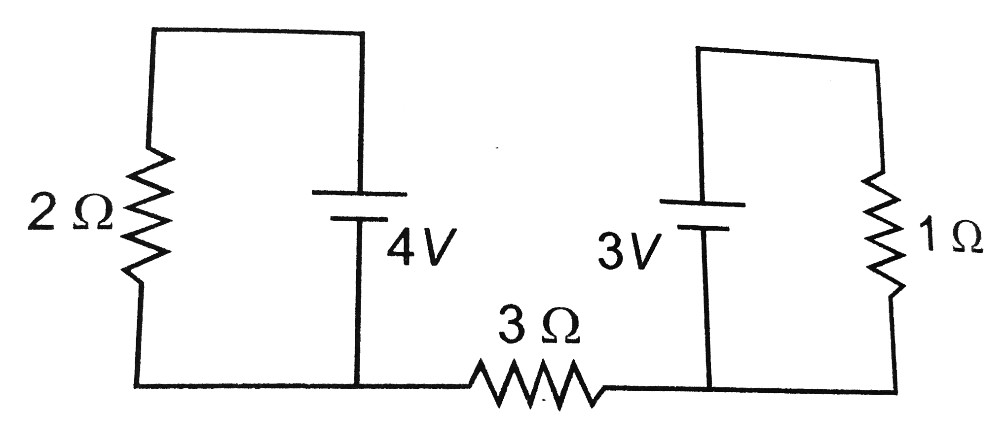
The potential difference across the 3 resistor shown in figure is
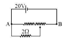
View SolutionThe given potentiometer has its wire of resistance 10Ω When the sliding contact is in the middle of the potentiometer wire, the potential drop across 2Ω resistor is :
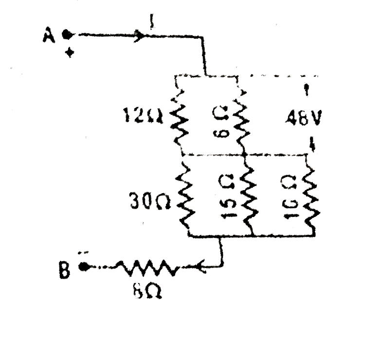
View SolutionIn the figure the potential difference across 6 ohm resistor is 48 V. Then the potential difference between A and B is
View SolutionA resistor, capacitor, switch, and ideal battery are in series. Originally the capacitor is uncharged. The switch is then closed, allowing current of flow
While the current is flowing, the potential difference across the resistor is
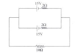
View SolutionFor the circuit shown in the figure what is the potential difference across the external resistance ?
View Solution

 .
.