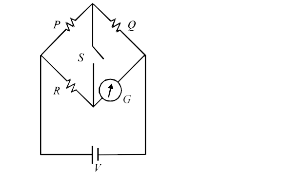
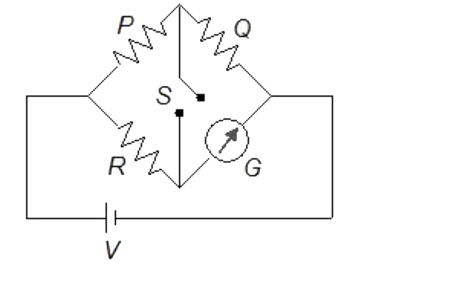
In the circuit P≠R, the reading of the galvanometer is same with switch S open or closed. Then
IR=IG
IP=IG
IQ=IG
IQ=IR
The correct Answer is:A
As there is no change in the reading of galvanometer with switch S open or closed. It implies that bridge is balanced current through S is zero and IR=IG,IP=IQ
Topper's Solved these Questions
- CURRENT ELECTRICITYBOOK - NARAYNACHAPTER - CURRENT ELECTRICITYEXERCISE - Level 6
43 Videos
- CURRENT ELECTRICITYBOOK - NARAYNACHAPTER - CURRENT ELECTRICITYEXERCISE - NCERT Based Questions
13 Videos
- COMMUNICATION SYSTEMBOOK - NARAYNACHAPTER - COMMUNICATION SYSTEMEXERCISE - Level-II(H.W)
25 Videos
- DUAL NATURE OF RADIATION AND MATTERBOOK - NARAYNACHAPTER - DUAL NATURE OF RADIATION AND MATTEREXERCISE - ASSERTION AND REASON
15 Videos
Similar Questions
Knowledge Check
In the circuit P≠R, the reading of the galvanometer is same with switch S open or closed. Then
 AIR=lGBIp=lGClQ=lGDIR=IQ
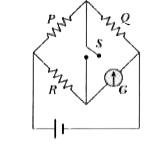
In the circuit shown P≠R the reading of galvonometer is same switch S open or closed. Then
 AIR=IGBIP=IGCIQ=IGDIQ=IS
In the circuit shown as P≠R and the reading of the galvanometer G is same with the switch open or closer. Then
 AIR=IGBIP=IGCIQ=IGDIQ=IR
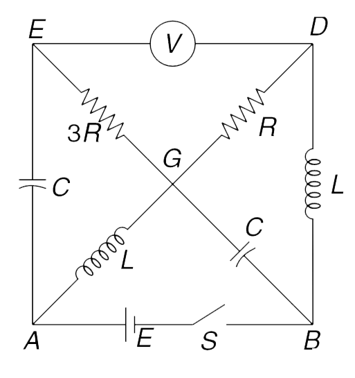
In the circuit shown, switch S is kept closed and the circuit is in steady state.
(a) Find reading of the ideal voltmeter
(b) Now the switch is opened. Find the reading of the voltmeter immedi- ately after the switch is opened.
(c) Fid the heat dissipated in resistance R after the switch is opened.
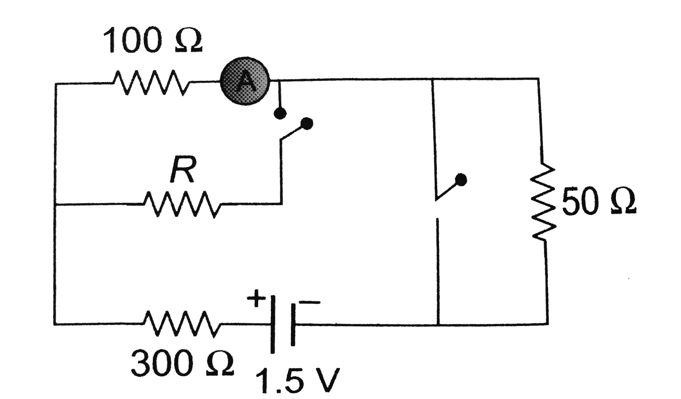
View SolutionIn the circuit shown in figure the reading of ammeter is the same with both switches open as with both closed. Then find the resistance R. (ammeter is ideal).
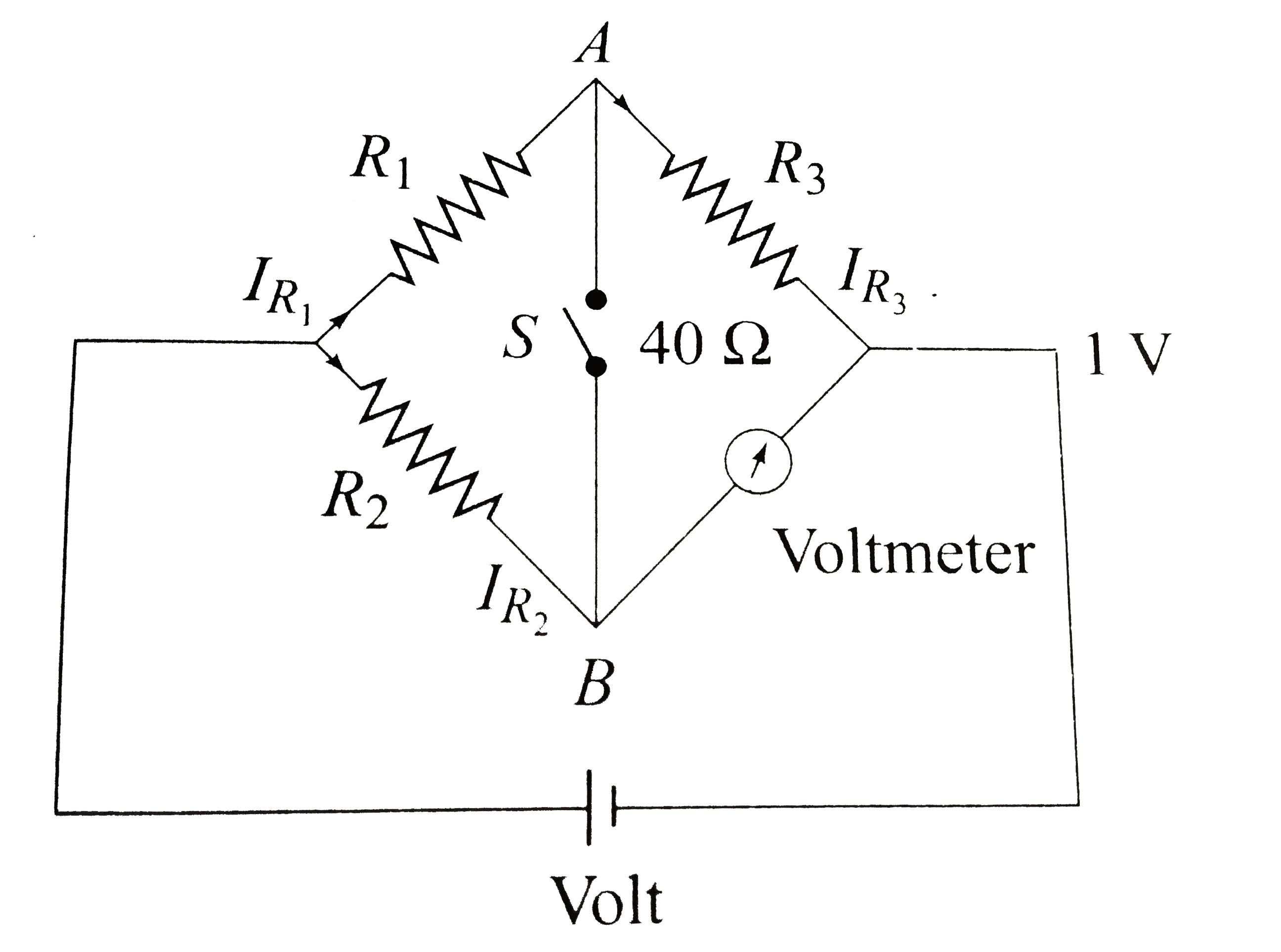
View SolutionIn the given circuit , R1≠R2 and the reading of the voltmeter is the same, irrespective of whether the switch S is open or closed. Then, which of the following is correct?
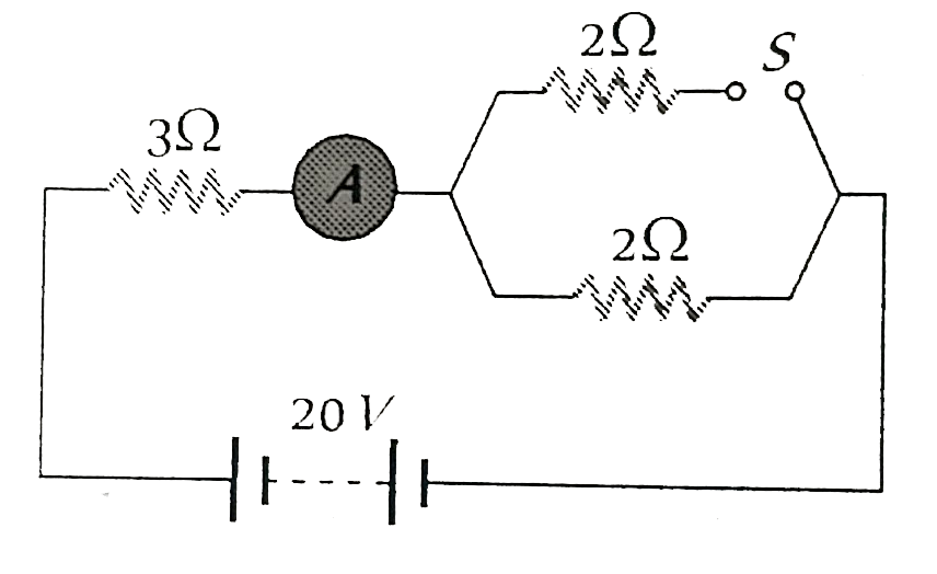
View SolutionIn the circuit shown, the reading of ammeter when switch S is open and when switch S is closed respectively are
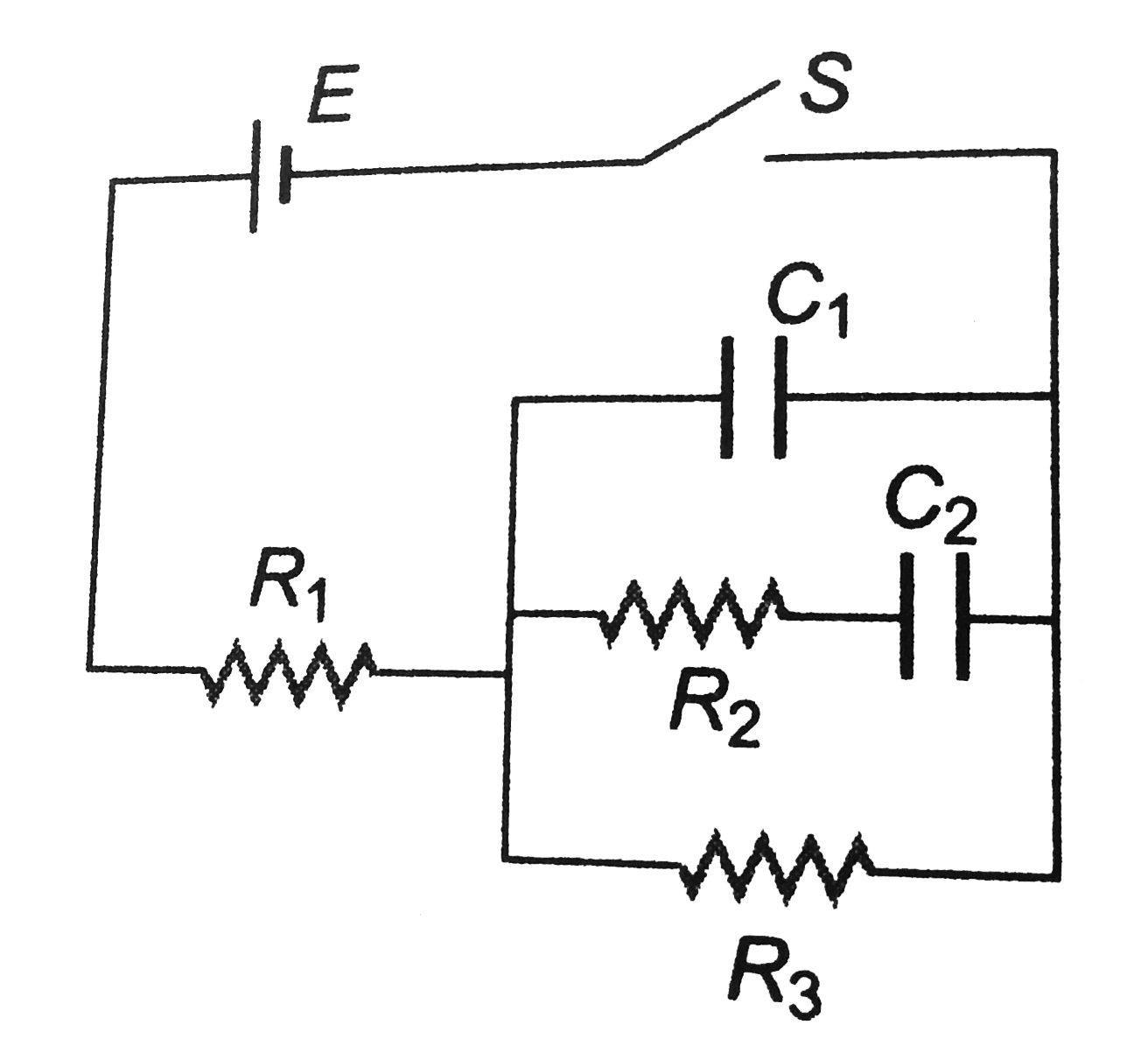
View SolutionIn the circuit diagram the current through the battery immediately after the switch S is closed is
View Solution

