The diagram shows a capacitor C and a resistor R connected in series to an AC source. V1 and V2 are voltmeters and A is ammeter
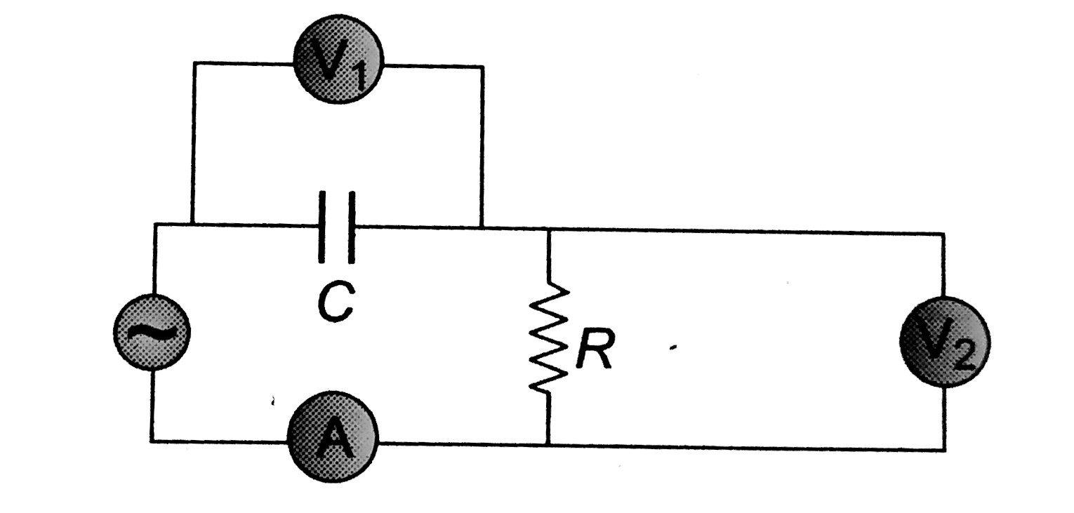
Now, consider the following statemensts :
(I) Reading in A and V2 are always in phase.
(II) Reading in V1 is ahead in phase with reading in V2,
(III) Reading in A and V1 are always in phase. Which of these statements are/is correct
I only
II only
I and II only
II and III only
The correct Answer is:A
Step by step video, text & image solution for The diagram shows a capacitor C and a resistor R connected in series to an AC source. V_(1) and V_(2) are voltmeters and A is ammeter Now, consider the following statemensts : (I) Reading in A and V_(2) are always in phase. (II) Reading in V_(1) is ahead in phase with reading in V_(2), (III) Reading in A and V_(1) are always in phase. Which of these statements are/is correct by Physics experts to help you in doubts & scoring excellent marks in Class 12 exams.
Topper's Solved these Questions
- BOOK - NARAYNACHAPTER - ALTERNATING CURRENTEXERCISE - LEVEL - I (H.W)23videos
ALTERNATING CURRENT
- BOOK - NARAYNACHAPTER - ALTERNATING CURRENTEXERCISE - LEVEL - II(H.W)13videos
ALTERNATING CURRENT
- BOOK - NARAYNACHAPTER - ALTERNATING CURRENTEXERCISE - LEVEL - V83videos
ALTERNATING CURRENT
- BOOK - NARAYNACHAPTER - ATOMIC PHYSICSEXERCISE - LEVEL-II (H.W)14videos
ATOMIC PHYSICS
Similar Questions
Knowledge Check
- Question 1 - Select One
An ammeter, voltmeter and a resistor are connected in series to a cell and the readings are noted as I and V. If another resistor R is connected in parallel with a voltmeter, then
AI and V increaseBI increasesCI and V will remain sameDI decreases - Question 2 - Select One
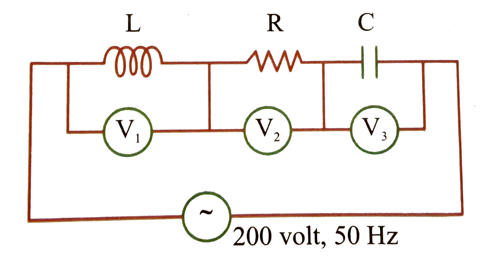
If the readings V1 and V3 are 10. volt each, then reading of V2 is:
 A0 voltB100 voltC200 voltDcannot be determined by given information
 - Question 3 - Select One or More
In the figure shows R=100Ω,L=2πH and C=8πμF are connected in series with an a.c. source of 200 volt and frequency f. V1 and V2 are two hot-wire voltmeters. If the reading of V1 and V2 are same, then
 Af=125HzBf=250πHzCCurrent through R is 2ADV1=V2=1000 volt
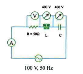
In the series LCR circuit as shown in the figure, the voltmeter V and ammeter A reading are
 View Solution
In the series LCR circuit as shown in the figure, the voltmeter V and ammeter A reading are
 View Solution
An ammeter and a voltmeter are connected in series to an ideal battery of emf E. If the ammeter reads I and voltmeter reading V, then
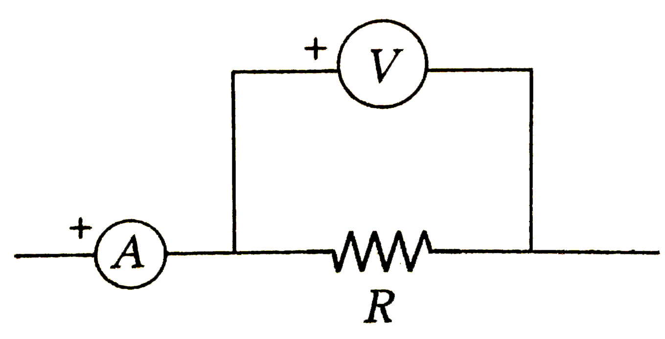
View SolutionAn ammeter A, a voltmeter V and a resistance R are connected as shown in the figure. If the voltmeter reading is 1.6V and the ammeter reading is 0.4A, then R is
 View Solution
A voltmeter reads V volts in an A.C. circuit then V is
View Solution


