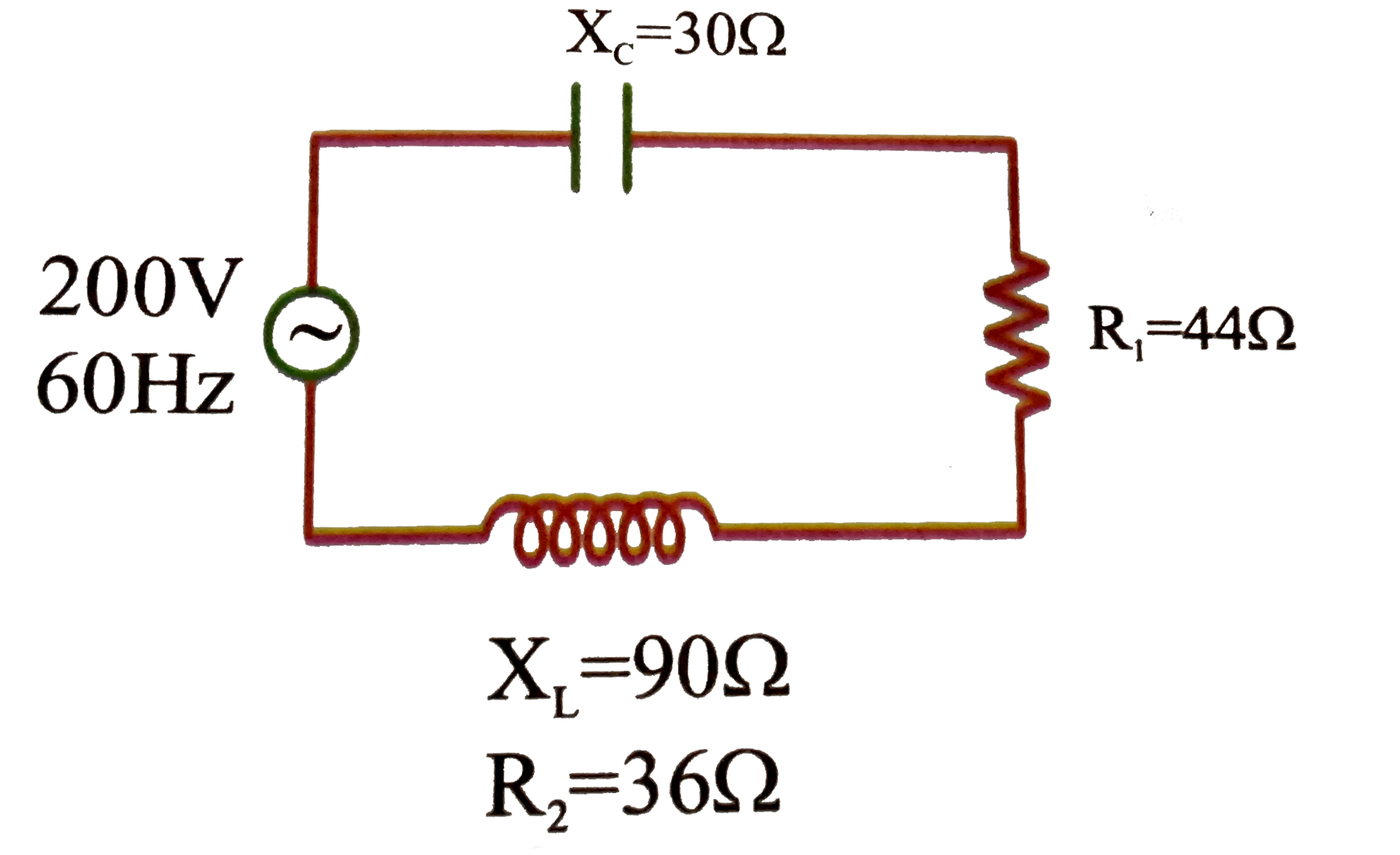
A series circuit connected across a 200V,60Hz line consists of a capacitive reactance 30Ω non inductive resistor of 44Ω and a coil of inductive reactance 90Ω and resistance 36Ω as shown in the diagram

The power used in the circuit is
320W
144W
160W
96W
The correct Answer is:A
Step by step video, text & image solution for A series circuit connected across a 200 V, 60 Hz line consists of a capacitive reactance 30 Omega non inductive resistor of 44 Omega and a coil of inductive reactance 90 Omega and resistance 36 Omega as shown in the diagram The power used in the circuit is by Physics experts to help you in doubts & scoring excellent marks in Class 12 exams.
Topper's Solved these Questions
- BOOK - NARAYNACHAPTER - ALTERNATING CURRENTEXERCISE - LEVEL - I (H.W)23videos
ALTERNATING CURRENT
- BOOK - NARAYNACHAPTER - ALTERNATING CURRENTEXERCISE - LEVEL - II(H.W)13videos
ALTERNATING CURRENT
- BOOK - NARAYNACHAPTER - ALTERNATING CURRENTEXERCISE - LEVEL - V83videos
ALTERNATING CURRENT
- BOOK - NARAYNACHAPTER - ATOMIC PHYSICSEXERCISE - LEVEL-II (H.W)14videos
ATOMIC PHYSICS
Similar Questions
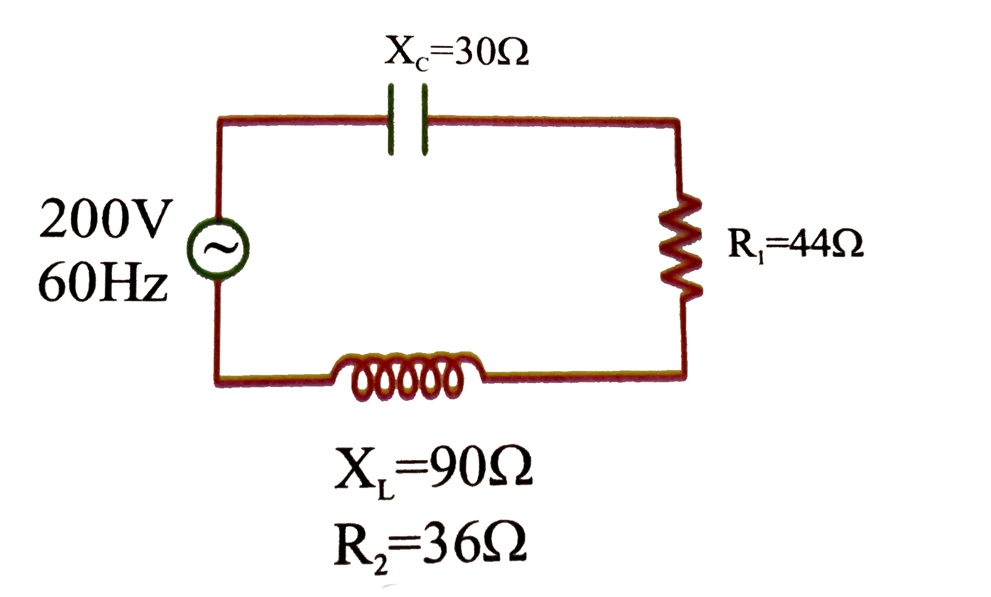
As given in the figure, n series circuit coanected across a 200V60HZ line coasists of a capacitor of capacitive reactance 30ohm, sa non-inductive resistar of 44ohm, and a coil of inductive reactance 90ohm and resistance 36ohm. The power dissipated (in watt) in the coil is
'(##CEN_KSR_PHY_JEE_C24_E01_021_Q11##)'View SolutionAn a.c. circuit an inductive reactance of 80Ωand a pure resistace of 60Ω. What is the impendance of the circuit?
View Solution
Knowledge Check
- Question 1 - Select One
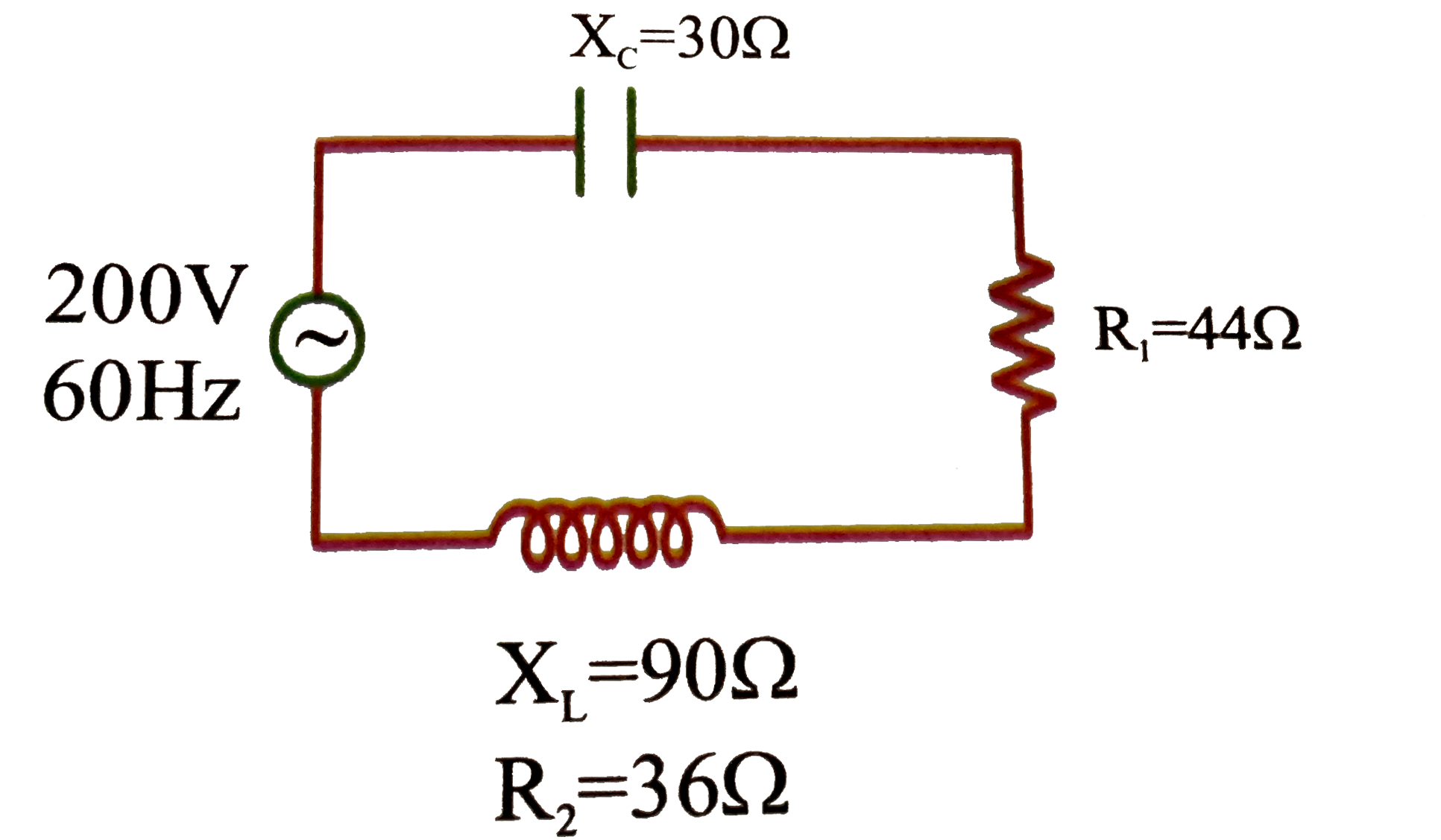
A series circuit connected across a 200V,60Hz line consists of a capacitive reactance 30Ω non inductive resistor of 44Ω and a coil of inductive reactance 90Ω and resistance 36Ω as shown in the diagram

The power dissipated in the inductance coil isAzeroB320WC144WD160W - Question 2 - Select One
A series circuit connected across a 200V,60Hz line consists of a capacitive reactance 30Ω non inductive resistor of 44Ω and a coil of inductive reactance 90Ω and resistance 36Ω as shown in the diagram

The potentail difference across the coil isA100vB194VC97VDzero - Question 3 - Select One
As given in the figure a series circuit connected across a 200 V, 60 Hz line consists of a capacitor of capacitive reactance 30Ω , a non-inductive resistor 44Ω , a coil of inductive reactance 9012 and another resistance of resistance 36Ω. The power dissipated in the circuit is
 A320 WB176 WC144 WD0 W
In L-R circuit, resistance is 8Ω and inductive reactance is 6Ω then impedance is:
View SolutionAn inductor of reactance 2Ω and a resistor of 4Ω are connected in series to the terminals of a 12 V (rms ) AC source. The power dissipated in the circuit is
View SolutionAn inductor of reactance 1 Ω and a resistor of 2 Ω are connected in series to the terminals of a 6 V (rms) a.c. source. The power dissipated in the circuit is
View SolutionA inductor of reactance 1Ω and a resistor of 2Ω are connected in series to the terminals of a 6 V (rms) a.c. source. The power dissipated in the circuit is
View SolutionIn a series LCR circuit, the total reactance is 4Ω and resistance is 3Ω . Its power factor is
View Solution

