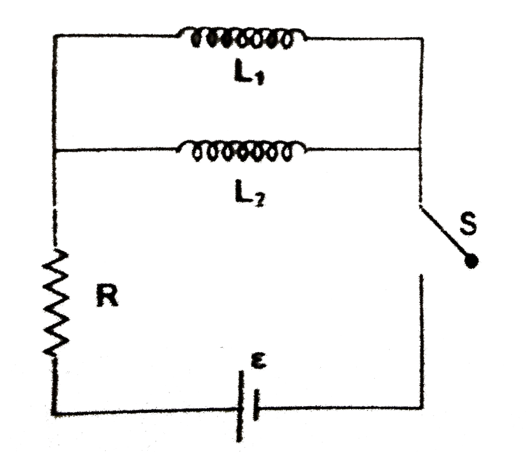
In the circuit shown, switch's is closed at t=0. then the ratio U1U2 of potential energy stored in the inductors L1 and L2 in steady state is
A
L1L2
B
L2L1
C
(L1L2)2
D
(L2L1)2
Video Solution
Text Solution
The correct Answer is:B
L1di1dt=L2di2dt ltbr> L1i1∫0di1=L2i2∫0di2
L1i1=L2i2 .(i)
i1+i2=i …(ii)
i1(1+L1L2)=i
⇒i1=(L2L1+L2)i and i2=(L1L1+L2)i ltbr> ∴U1U2=12L1i2112L2i22=L1L22L2L21=L2L1
|
Updated on:21/07/2023
Topper's Solved these Questions
- BOOK - FIITJEECHAPTER - TEST PAPERSEXERCISE - PHYSICS747videos
TEST PAPERS
- BOOK - FIITJEECHAPTER - SIMPLE HARMONIC MOTIONEXERCISE - Assignment Problems (Objective) (Level-II)20videos
SIMPLE HARMONIC MOTION
- BOOK - FIITJEECHAPTER - WORK, ENERGY AND POWER EXERCISE - COMPREHENSIONS ( Comprehension-II)5videos
WORK, ENERGY AND POWER
Similar Questions
Knowledge Check
- Question 1 - Select One
In the circuit shown, the switch is closed at t=0, the currents I1,I2 and I3 are
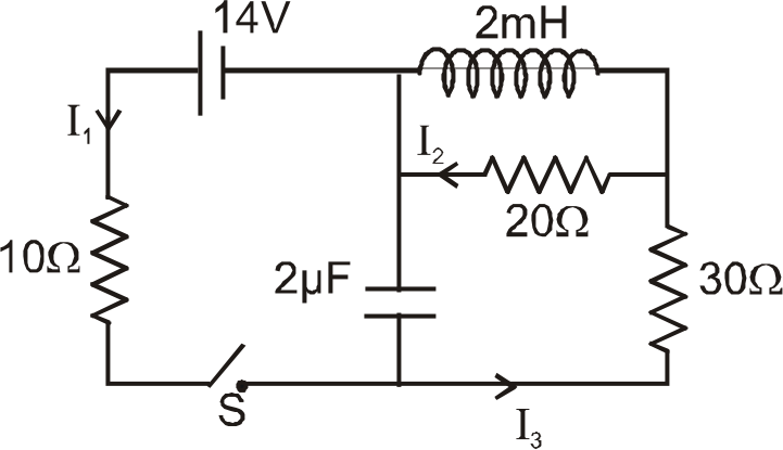 A1.4A,0,0B1.4 A,0.70 A,0.70 AC0,0,0D1.2A,0.6A,0.6A
 - Question 2 - Select One
In the circuit shown, the switch 'S' is closed at t=0. Then the current through the battery steady state reached is
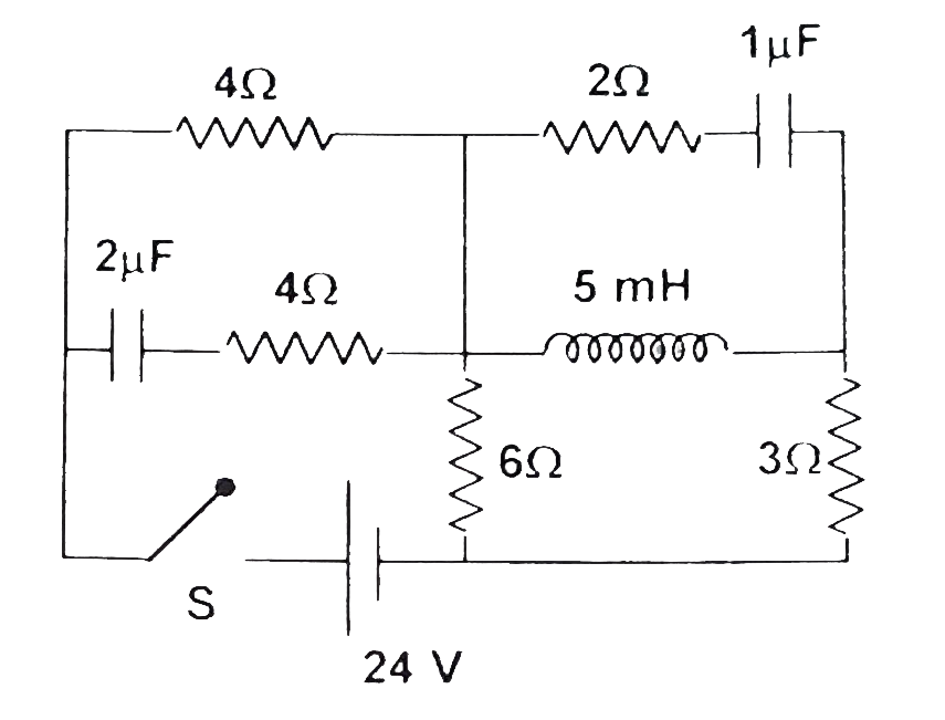 A2AB4AC6AD8A
 - Question 3 - Select One or More
In the circuit as shown in figure the switch is closed at t=0.
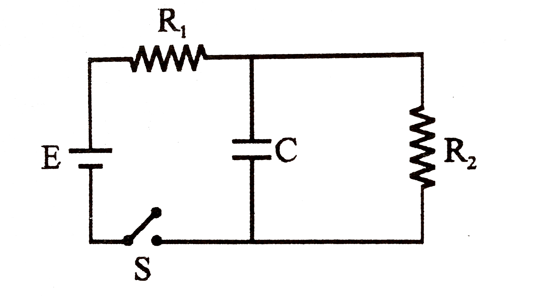
At the instant of closing the switchAthe battery delivers maximum currentBno current flows through CCvoltage drop across R2 is zeroDthe current through the battery decreases with time finally becomes zero
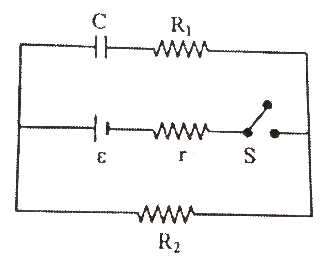
In given circuit, switch S is closed at t=0 . The charge on the capacitor ar steady state will be
 View Solution
In the circuit shown in figure switch S is closed at time t=0
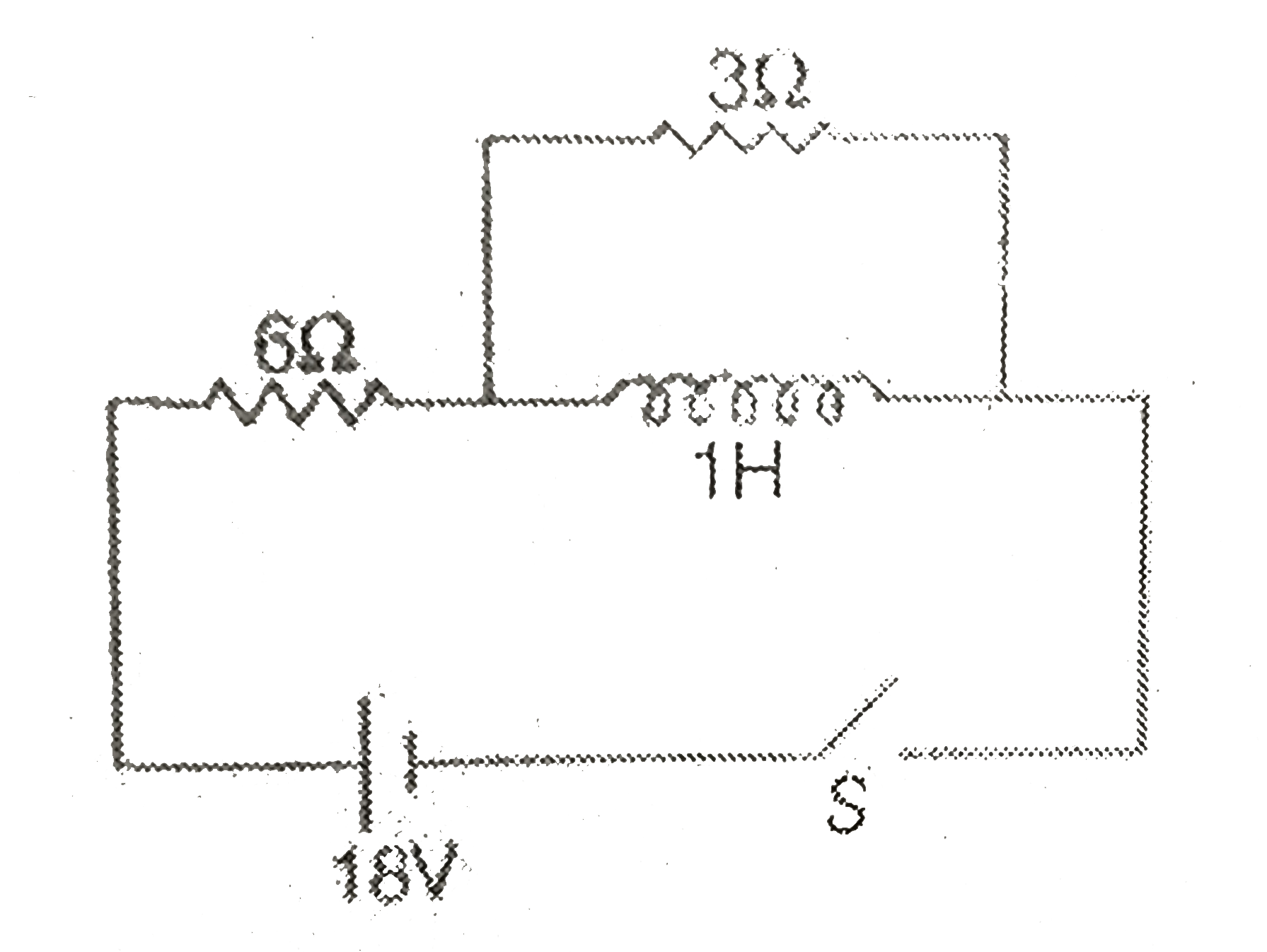
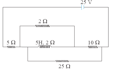
At what time current through 3Ω resistance and 1H inductor are equal?View SolutionIn the circuit shown, what is the energy stored in the coil at steady state is closed to?
 View Solution
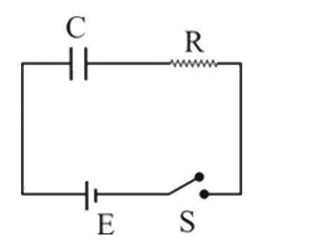
The capacitor shown in the figure is initially unchanged, the battery is ideal. The switch S is closed at time t= 0, then the time after which the energy stored in the capacitor becomes one - fourth of the energy stored in it in steady - state is :
 View Solution
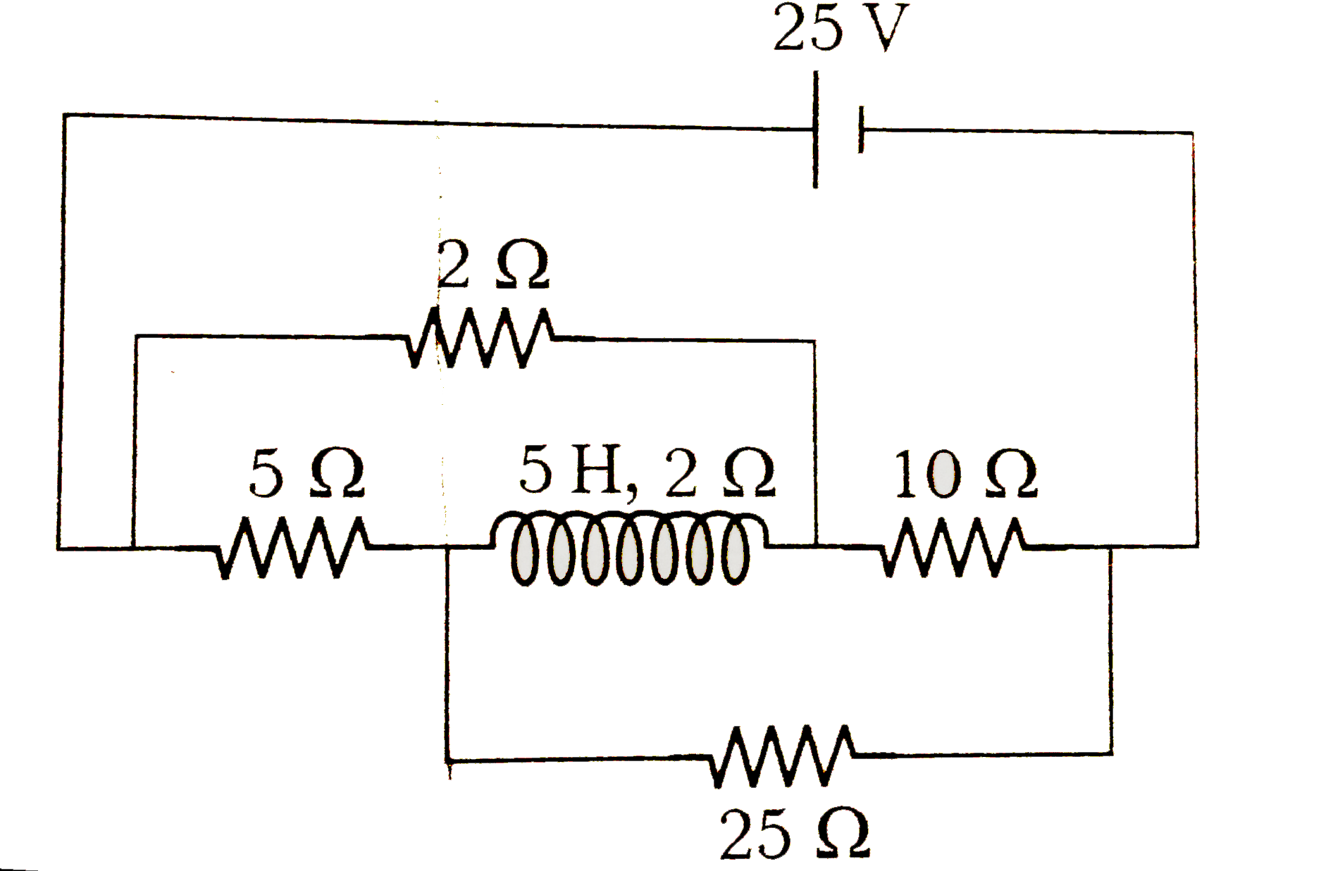
In the circuit shown , what is the energy stored in the coil at steady state?
 View Solution


_PHY_E06_157_Q01.png)