An experimental setup of verification of photoelectric effect is shown in the diagram. The voltage across the electrodes is measured with the help of an ideal voltmeter, and which can be varied by moving jockey 'j' on the potentiometer wire. The battery used in potentiometer circuit is of 20 V and its internal resistance is 2Ω. The resistance of 100 cm long potentiometer wire is 8Ω
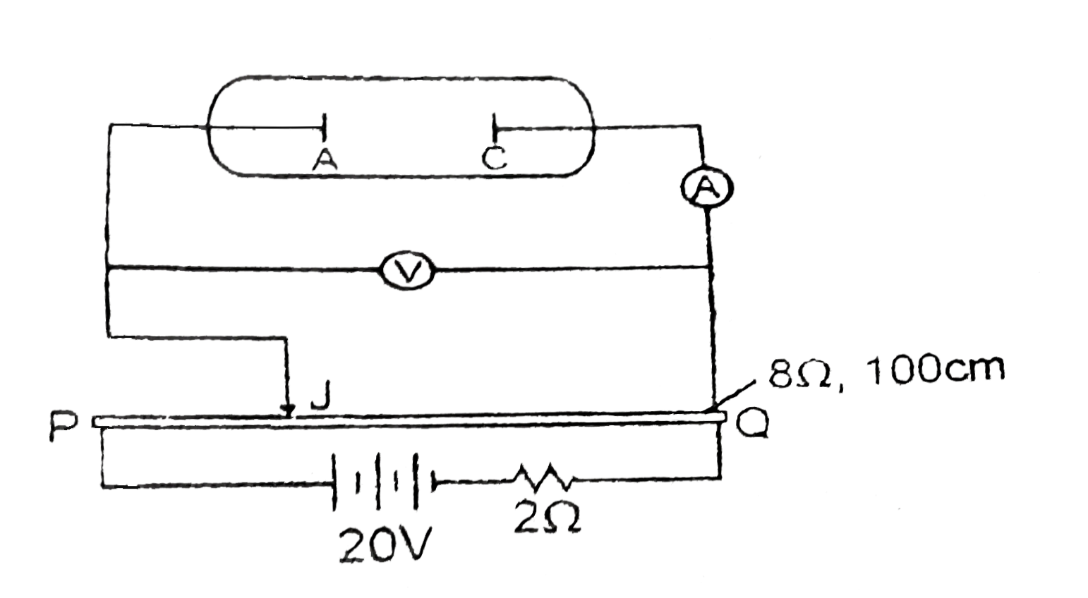
The photocurrent is measured with the help of an ideal ammeter. Two plates of potassium oxide of area 50cm2 at separation 0.5mm are used in the vacuum tube. Photo current in the circuit is very small so we can treat potentiometer circuit an independent circuit.
The wavelengths of various colours is as follows :
Light1Violet2Blue3Green4Yellow5Orange6RedλinÅ→4000−45004500−50005000−55005500−60006000−650006500−70000.
Which of the following colour may not give photoelectric effect from this cathode :
Green
Violet
Red
Orange
The correct Answer is:C
The range of wavelength for red light is beyond the wavelength of incident light.
Topper's Solved these Questions
- BOOK - RESONANCECHAPTER - DAILY PRACTICE PROBLEMEXERCISE - DPP No.4520videos
DAILY PRACTICE PROBLEM
- BOOK - RESONANCECHAPTER - DAILY PRACTICE PROBLEMEXERCISE - DPP No.4611videos
DAILY PRACTICE PROBLEM
- BOOK - RESONANCECHAPTER - DAILY PRACTICE PROBLEMEXERCISE - DPP No.4320videos
DAILY PRACTICE PROBLEM
- BOOK - RESONANCECHAPTER - CURRENT ELECTRICITYEXERCISE - High Level Problems (HIP)21videos
CURRENT ELECTRICITY
- BOOK - RESONANCECHAPTER - ELECTRO MAGNETIC WAVESEXERCISE - Exercise 327videos
ELECTRO MAGNETIC WAVES
Similar Questions
An experimental setup of verification of photoelectric effect is shown in the diagram. The voltage across the electrode is measured with the help of an ideal voltmetar, and which can be varied by moving jockey 'J' on the potentiometer wire. The battery used in potentiometer circuit is of 20 V and its internal resistance is 2ω. The resistance of 100cm long potentiometer wire is 8ω. The photo current is measured with the help of an ideal ammeter. Two plates of potassium oxide of area 50cm2 at separation 0.5mm are used in the vacuum tube. Photo current in the circuit is very small so we can treat potentiometer circuit an indepdent circuit. The wavelength of various colours is as follows :
_E01_158_Q01.png)
∣∣ ∣∣Light1Violet2Blue3Green4Yellow5Orange6RedλinÅ→4000−45004500−50005000−55005500−60006000−65006500−7000∣∣ ∣∣
When other light falls on the anode plate the ammeter reading remains zero till, jockey till, jockey is moved from the end P to the middle point on the wire PQ. Thereafter the deflection is recorded in the ammeter. The maximum kinetic energy of the emitted electron is :View SolutionAn experimental setup of verification of photoelectric effect is shown in the diagram. The voltage across the electrode is measured with the help of an ideal voltmetar, and which can be varied by moving jockey 'J' on the potentiometer wire. The battery used in potentiometer circuit is of 20 V and its internal resistance is 2ω. The resistance of 100cm long potentiometer wire is 8ω. The photo current is measured with the help of an ideal ammeter. Two plates of potassium oxide of area 50cm2 at separation 0.5mm are used in the vacuum tube. Photo current in the circuit is very small so we can treat potentiometer circuit an indepdent circuit. The wavelength of various colours is as follows :
_E01_156_Q01.png)
∣∣ ∣∣Light1Violet2Blue3Green4Yellow5Orange6RedλinÅ→4000−45004500−50005000−55005500−60006000−65006500−7000∣∣ ∣∣
When radiation falls on the cathode plate a current of 2μA is recorded in the ammeter. Assuming that the vecuum tube setup follows ohm's law, the equivalent resistance of vacuum tube operating in this case when jockey is at end P.View Solution
Knowledge Check
- Question 1 - Select One
An experimental setup of verification of photoelectric effect is shown in the diagram. The voltage across the electrodes is measured with the help of an ideal voltmeter, and which can be varied by moving jockey 'j' on the potentiometer wire. The battery used in potentiometer circuit is of 20 V and its internal resistance is 2Ω. The resistance of 100 cm long potentiometer wire is 8Ω
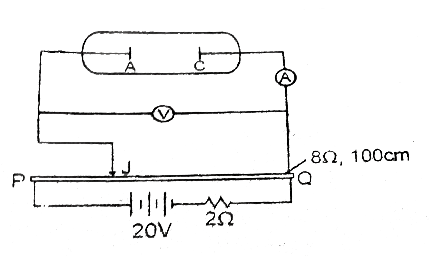
The photocurrent is measured with the help of an ideal ammeter. Two plates of potassium oxide of area 50cm2 at separation 0.5mm are used in the vacuum tube. Photo current in the circuit is very small so we can treat potentiometer circuit an independent circuit.
The wavelengths of various colours is as follows :
Light1Violet2Blue3Green4Yellow5Orange6RedλinÅ→4000−45004500−50005000−55005500−60006000−650006500−70000.
It is found that ammeter current remains unchanged (2μA) even when the jockey is moved from the end 'P' to the middle point of the potentiometer wire. Assuming all the incident photons eject electron and the power of the light incident is 4×10⁻⁶W. Then the colour of the incident light isAGreenBVioletCRedDOrange - Question 2 - Select One
An experimental setup of verification of photoelectric effect is shown in the diagram. The voltage across the electrodes is measured with the help of an ideal voltmeter, and which can be varied by moving jockey 'j' on the potentiometer wire. The battery used in potentiometer circuit is of 20 V and its internal resistance is 2Ω. The resistance of 100 cm long potentiometer wire is 8Ω

The photocurrent is measured with the help of an ideal ammeter. Two plates of potassium oxide of area 50cm2 at separation 0.5mm are used in the vacuum tube. Photo current in the circuit is very small so we can treat potentiometer circuit an independent circuit.
The wavelengths of various colours is as follows :
Light1Violet2Blue3Green4Yellow5Orange6RedλinÅ→4000−45004500−50005000−55005500−60006000−650006500−70000.
When other light falls on the anode plate the ammeter reading remains zero till. jockey is moved from the end P to the middle point of the wire PQ. There after the deflection is recorded in the ammeter. The maximum kinetic energy of the emitted electron isA16 eVB8 eVC4 eVD10 eV - Question 3 - Select One
An experimental setup of verification of photoelectric effect is shown in the diagram. The voltage across the electrode is measured with the help of an ideal voltmetar, and which can be varied by moving jockey 'J' on the potentiometer wire. The battery used in potentiometer circuit is of 20 V and its internal resistance is 2ω. The resistance of 100cm long potentiometer wire is 8ω. The photo current is measured with the help of an ideal ammeter. Two plates of potassium oxide of area 50cm2 at separation 0.5mm are used in the vacuum tube. Photo current in the circuit is very small so we can treat potentiometer circuit an indepdent circuit. The wavelength of various colours is as follows :
_E01_155_Q01.png)
∣∣ ∣∣Light1Violet2Blue3Green4Yellow5Orange6RedλinÅ→4000−45004500−50005000−55005500−60006000−65006500−7000∣∣ ∣∣
The number of electrons appeared on the surface of the cathode plate, when the jockey is connected at the ened 'P' of the potentiometer wire. Assume that no radiation is falling on the plates.A8.85×106B11.0625×109C8.85×109D0
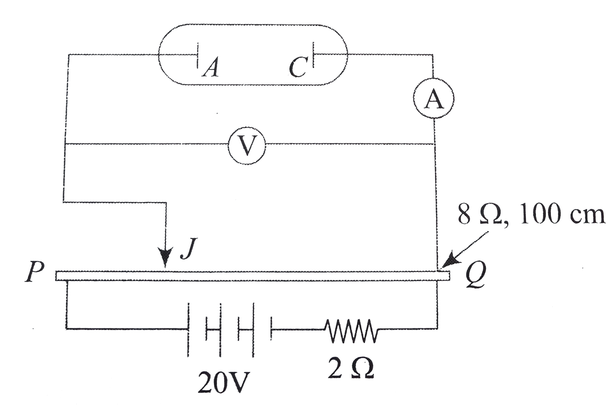
An experimental setup of verification of photoelectric effect is shown if Fig. The voltage across the electrodes is measured with the help of an ideal voltmeter, and which can be varied by moving jockey J on the potentiometer with wire. The battery used in potentiometer circuit is of 20 V and its internal resistance is 2Ω. The resistance of 100 cm long potentiometer wire is 8Ω.
The photocurrent is measured with the help of an ideal ammeter. Two plates of potassium oxide of area 50cm2 at separation 0.5mm are used in the vacuum tube. Photocurrent in the circuit is very small, so we can treat the potentiometer circuit as an independent circuit. The wavelength of various colors is as follows:
Q. Which of the following colors may not give photoelectric effect for this cathode?View Solution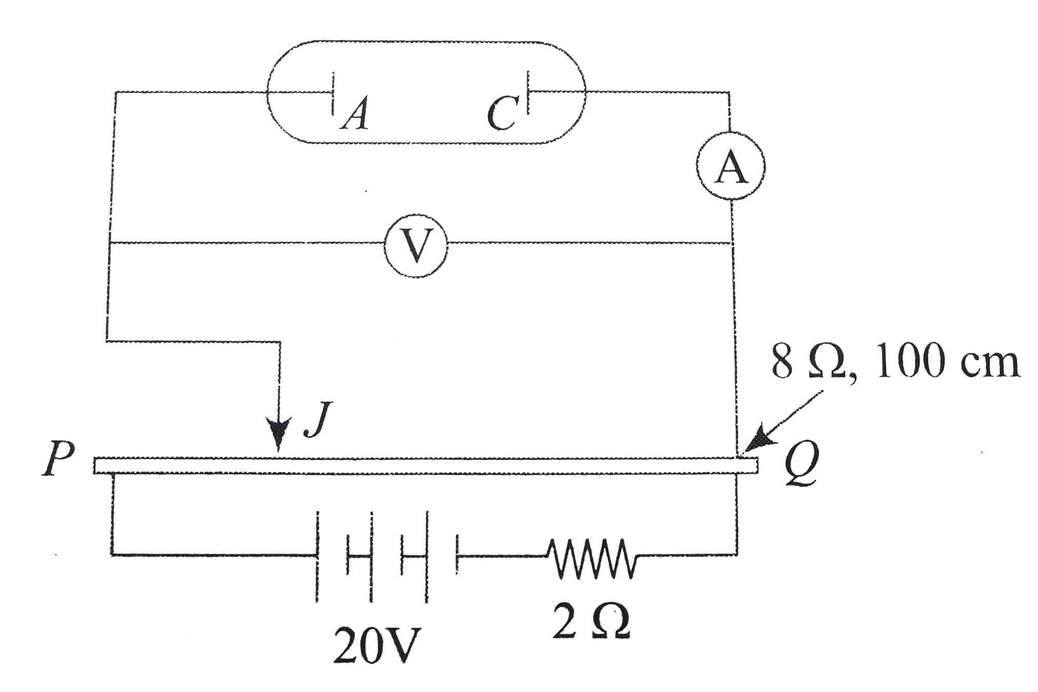
An experimental setup of verification of photoelectric effect is shown if Fig. The voltage across the electrodes is measured with the help of an ideal voltmeter, and which can be varied by moving jockey J on the potentiometer with wire. The battery used in potentiometer circuit is of 20 V and its internal resistance is 2Ω. The resistance of 100 cm long potentiometer wire is 8Ω.
The photocurrent is measured with the help of an ideal ammeter. Two plates of potassium oxide of area 50cm2 at separation 0.5mm are used in the vacuum tube. Photocurrent in the circuit is very small, so we can treat the potentiometer circuit as an independent circuit. The wavelength of various colors is as follows:
Q. Calculate the number of electrons that appear on the surface of the cathode plate, when the jockey is connected at the end P of the potentiometer wire. Assume that no radiation is falling on the plates.View Solution
An experimental setup of verification of photoelectric effect is shown if Fig. The voltage across the electrodes is measured with the help of an ideal voltmeter, and which can be varied by moving jockey J on the potentiometer with wire. The battery used in potentiometer circuit is of 20 V and its internal resistance is 2Ω. The resistance of 100 cm long potentiometer wire is 8Ω.
The photocurrent is measured with the help of an ideal ammeter. Two plates of potassium oxide of area 50cm2 at separation 0.5mm are used in the vacuum tube. Photocurrent in the circuit is very small, so we can treat the potentiometer circuit as an independent circuit. The wavelength of various colors is as follows:
Q. When radiation falls on the cathode plate, a current of 2μA is recorded in the ammeter. Assuming that the vacuum tube setup sollows Ohm's law, the equivalent resistance of vacuum tube operating in this case when jockey is at end P isView Solution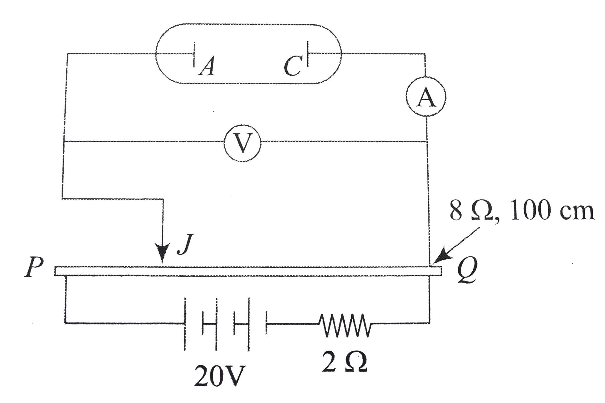
An experimental setup of verification of photoelectric effect is shown if Fig. The voltage across the electrodes is measured with the help of an ideal voltmeter, and which can be varied by moving jockey J on the potentiometer with wire. The battery used in potentiometer circuit is of 20 V and its internal resistance is 2Ω. The resistance of 100 cm long potentiometer wire is 8Ω.
The photocurrent is measured with the help of an ideal ammeter. Two plates of potassium oxide of area 50cm2 at separation 0.5mm are used in the vacuum tube. Photocurrent in the circuit is very small, so we can treat the potentiometer circuit as an independent circuit. The wavelength of various colors is as follows:
Q. When other light falls on the anode plate, the ammeter reading remains zero till jockey is moved from the end P to the middle point of the wire PQ. Thereafter, the deflection is recorded in the ammeter. The maximum kinetic energy of the emitted electron isView Solution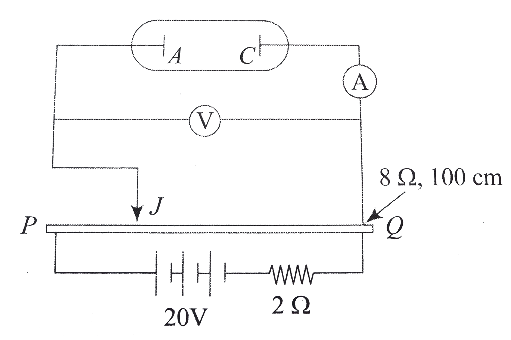
An experimental setup of verification of photoelectric effect is shown if Fig. The voltage across the electrodes is measured with the help of an ideal voltmeter, and which can be varied by moving jockey J on the potentiometer with wire. The battery used in potentiometer circuit is of 20 V and its internal resistance is 2Ω. The resistance of 100 cm long potentiometer wire is 8Ω.
The photocurrent is measured with the help of an ideal ammeter. Two plates of potassium oxide of area 50cm2 at separation 0.5mm are used in the vacuum tube. Photocurrent in the circuit is very small, so we can treat the potentiometer circuit as an independent circuit. The wavelength of various colors is as follows:
Q. It is found that ammeter current remains unchanged (2μA) even when the jockey is moved from the end P to the middle point of the potentiometer wire. Assuming that all the incident photons eject electrons and the power of the light incident is 4×10⁻⁶ W. Then, the color of the incident light isView Solution

