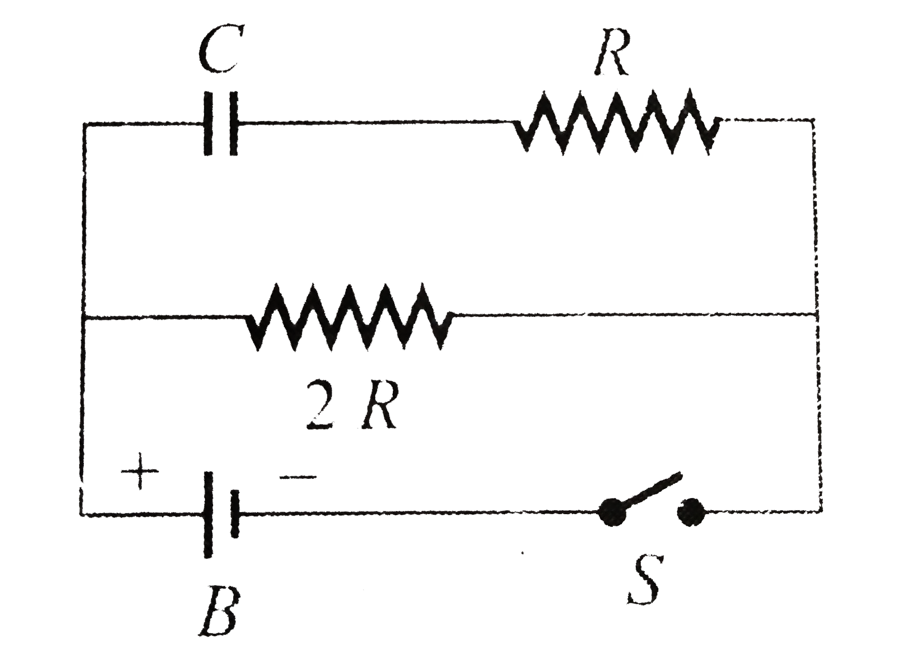
The circuit was in the shown state for a long time. Now if the switch S is closed then the net charge that flows through the switch S, will be

4003μC
100μC
1003μC
50μC
The correct Answer is:D
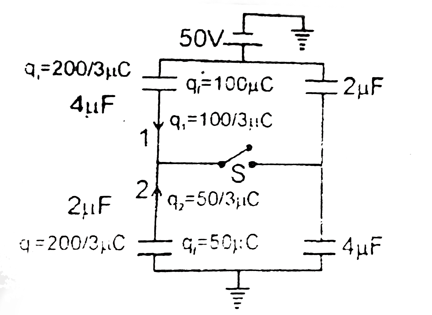
Initial and final charges are marked on 4μf and 2μf capacitors as shown
Hence charge passing through segment 1 and 2 are
q1=1003μC⇒q1=503μC
∴ charge through switch =q1+q2=50μC.
Topper's Solved these Questions
- DAILY PRACTICE PROBLEMBOOK - RESONANCECHAPTER - DAILY PRACTICE PROBLEMEXERCISE - DPP No.56
20 Videos
- DAILY PRACTICE PROBLEMBOOK - RESONANCECHAPTER - DAILY PRACTICE PROBLEMEXERCISE - DPP No.57
9 Videos
- DAILY PRACTICE PROBLEMBOOK - RESONANCECHAPTER - DAILY PRACTICE PROBLEMEXERCISE - DPP No.54
9 Videos
- CURRENT ELECTRICITYBOOK - RESONANCECHAPTER - CURRENT ELECTRICITYEXERCISE - High Level Problems (HIP)
21 Videos
- ELECTRO MAGNETIC WAVESBOOK - RESONANCECHAPTER - ELECTRO MAGNETIC WAVESEXERCISE - Exercise 3
27 Videos
Similar Questions
Consider the situation shown in the figure. The switch S is open for a long time and then closed and again steady state reached then
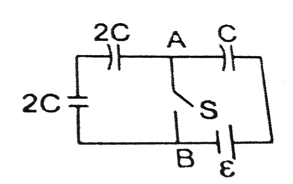
(a) Find the charge flown through the battery after the switch S is closed.
(b) Find the charge flown through the switch S from B to A.
(c) Find the work done by the battery after the switch S is closed.
(d) Find the change in energy stored in the system of capacitors.
(e) Find the heat developed in the system after the switch S is closed.
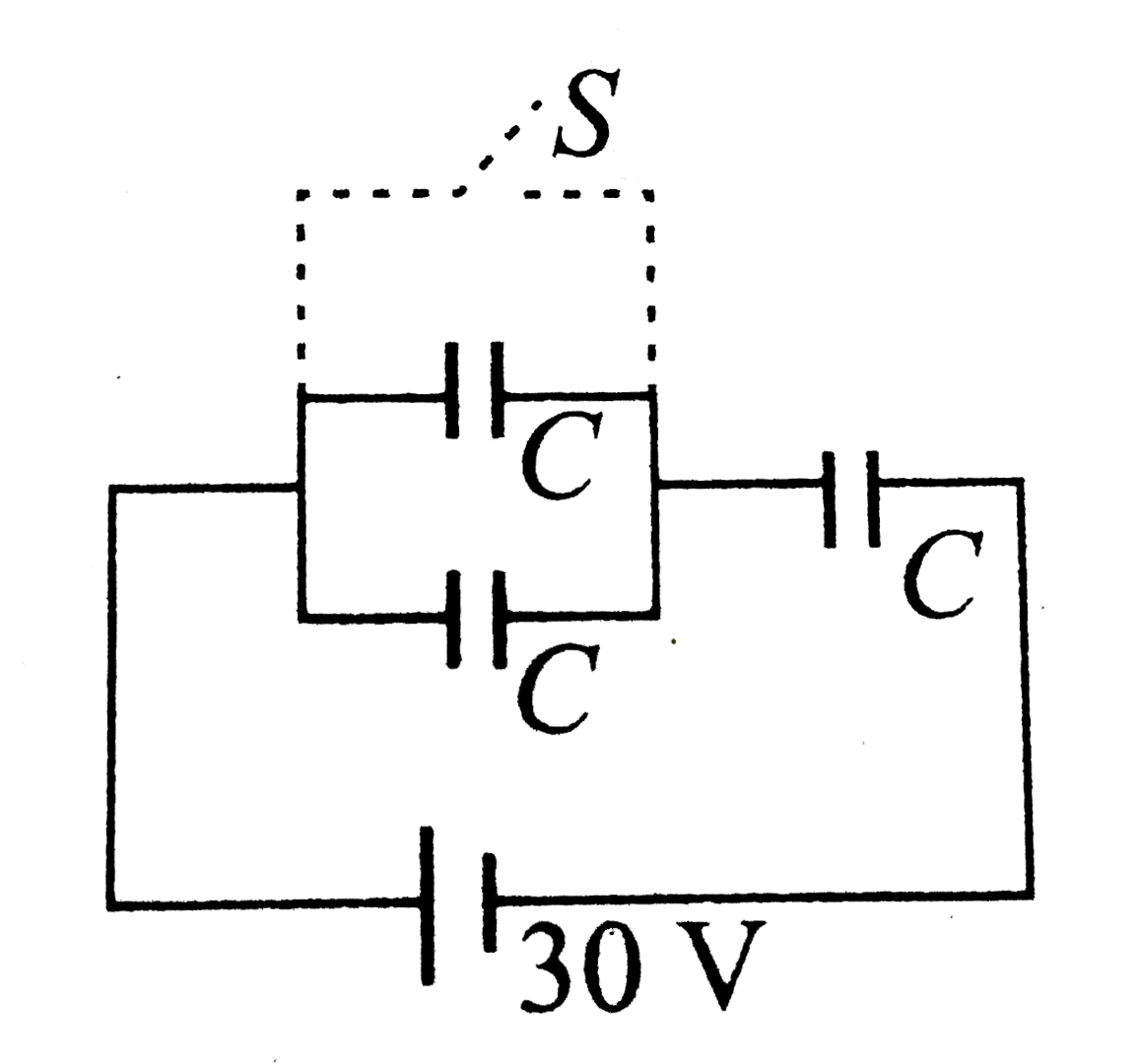
View SolutionThree capacitors each having capacitance C=2μF are connected with a battery of emf30V as shown in. when the switch S is closed, find
a. the amount of charge flowing through the battery ,
b. the heat generated in the circuit,
c. the energy supplied by the battery,
d. the amount of charge flowing through the switch S.
 .
.
View Solution
Knowledge Check
The circuit was in the shown state from a long time. Now the switch S is closed. The charged that flows through the switch is
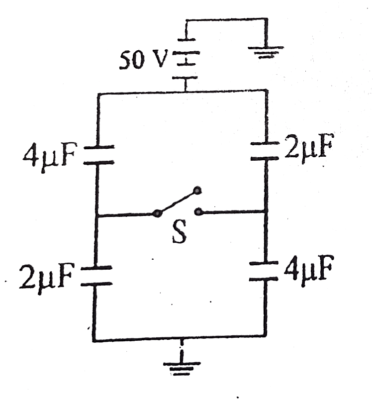 A4003μCB100μCC50μCD1003μC
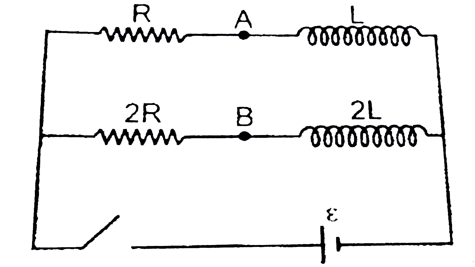
In given LR circuit the switch S is closed at time t=0 thenAThe ratio of induced emfs in the inductors of inductance L and 2L will be constantBThe ratio of induced emfs in the inductor of inductance L and 2L will be time varyingCthe potential difference VA−VB increases with timeDThe potential difference VA−VB will be constantWhen the switch S is closed in the given circuit, the current passed through it is
 A2AB1AC0.6ADzero
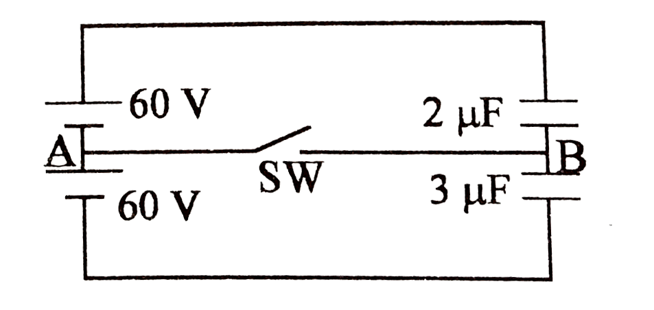
In the circuit shown in the figure, intially SW is open. When the switch is closed, the charge passing through the switch in the direction_________to_______.
View Solution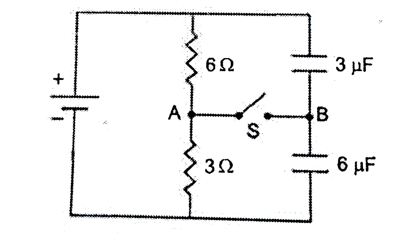
In the circuit shown above, when then switch S is closed,
View SolutionIn the circuit as shown in figure the switch is closed at t=0.
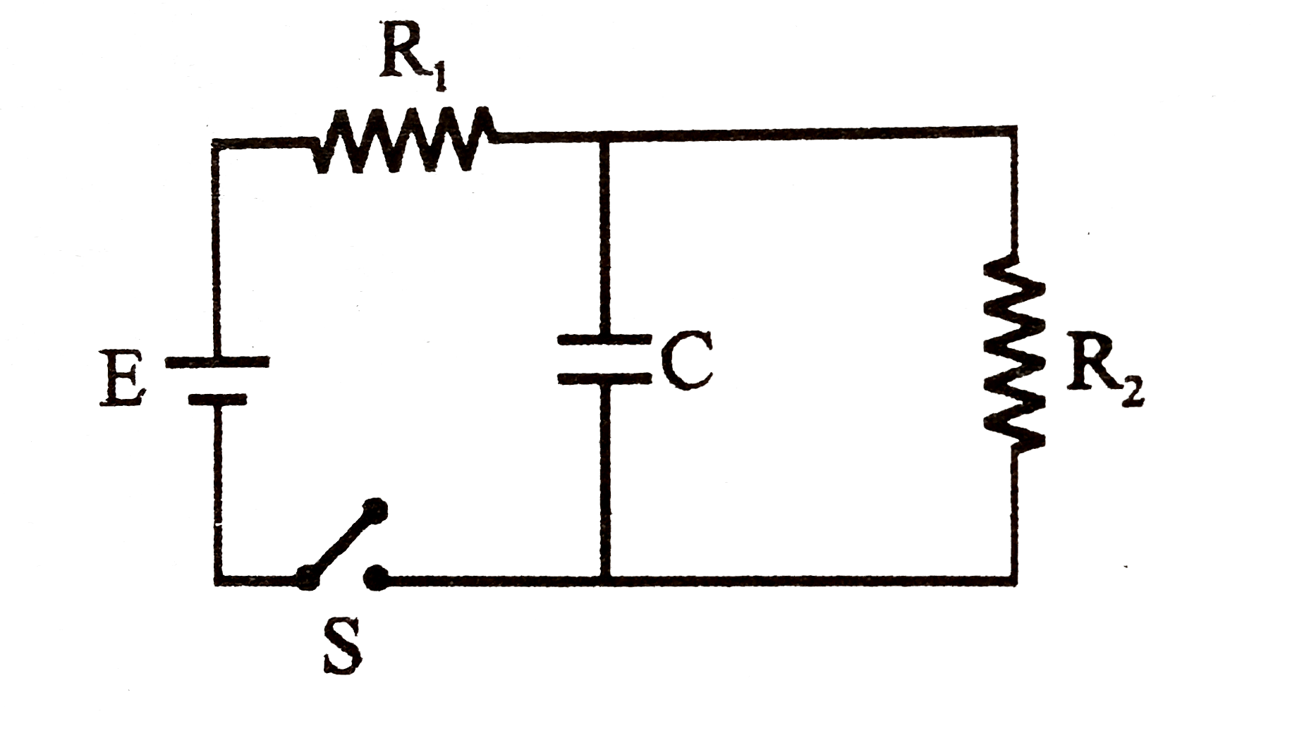
At the instant of closing the switch
View SolutionIn the circuit shown in fig, if the switch S is closed at t=0 , the capacitor charges with a time constant
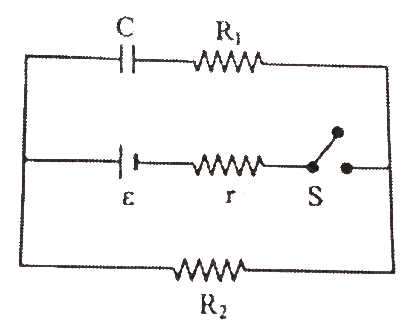
View SolutionIn given circuit, switch S is closed at t=0 . The charge on the capacitor ar steady state will be
View Solution
