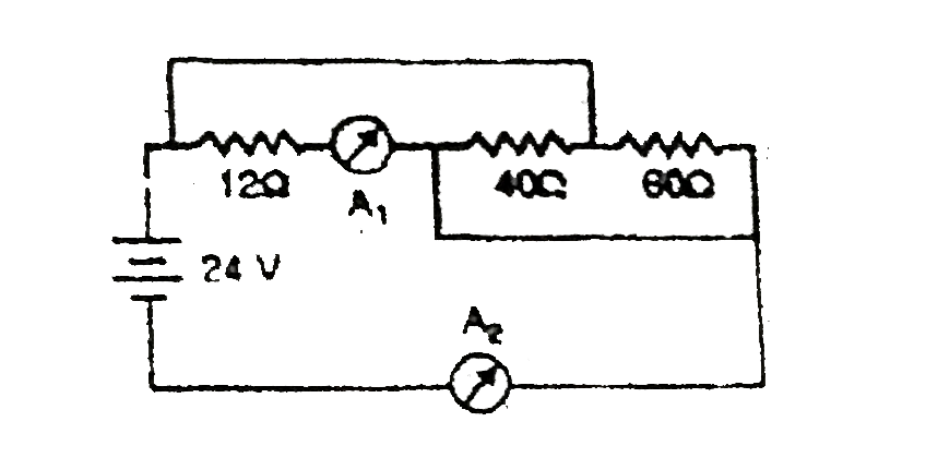
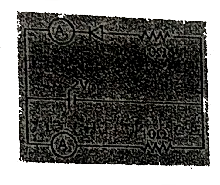
In the circuit of figure A1 and A2 are ideal ammeters. Then the reading in ammeter A2 is
A
0.4A
B
0.6A
C
2.0A
D
3.0A
Video Solution
Text Solution
The correct Answer is:D
1Req=1120+140+160=10+3+2120⇒Req=8Ω
i2=248=3Amp
|
Topper's Solved these Questions
Similar Questions
Knowledge Check
In the circuit shown in figure, reading of ammeter will
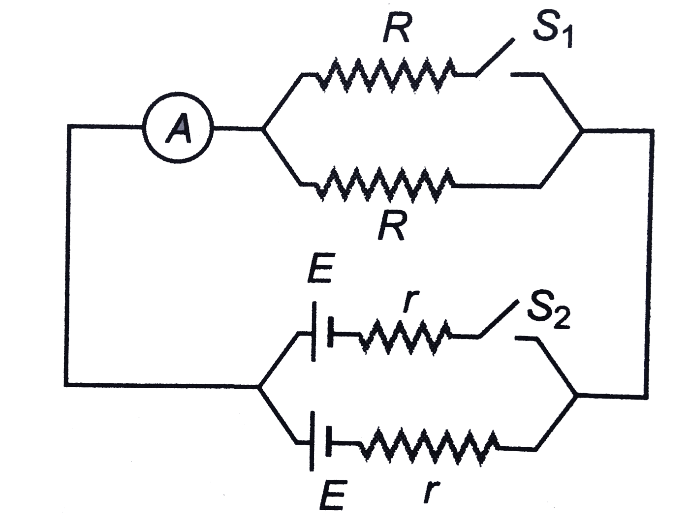 Ashows no deflection if S1 is closedBdecrease if S2 is closedCincrease if S2 is closedDdecrease if S2 is closed
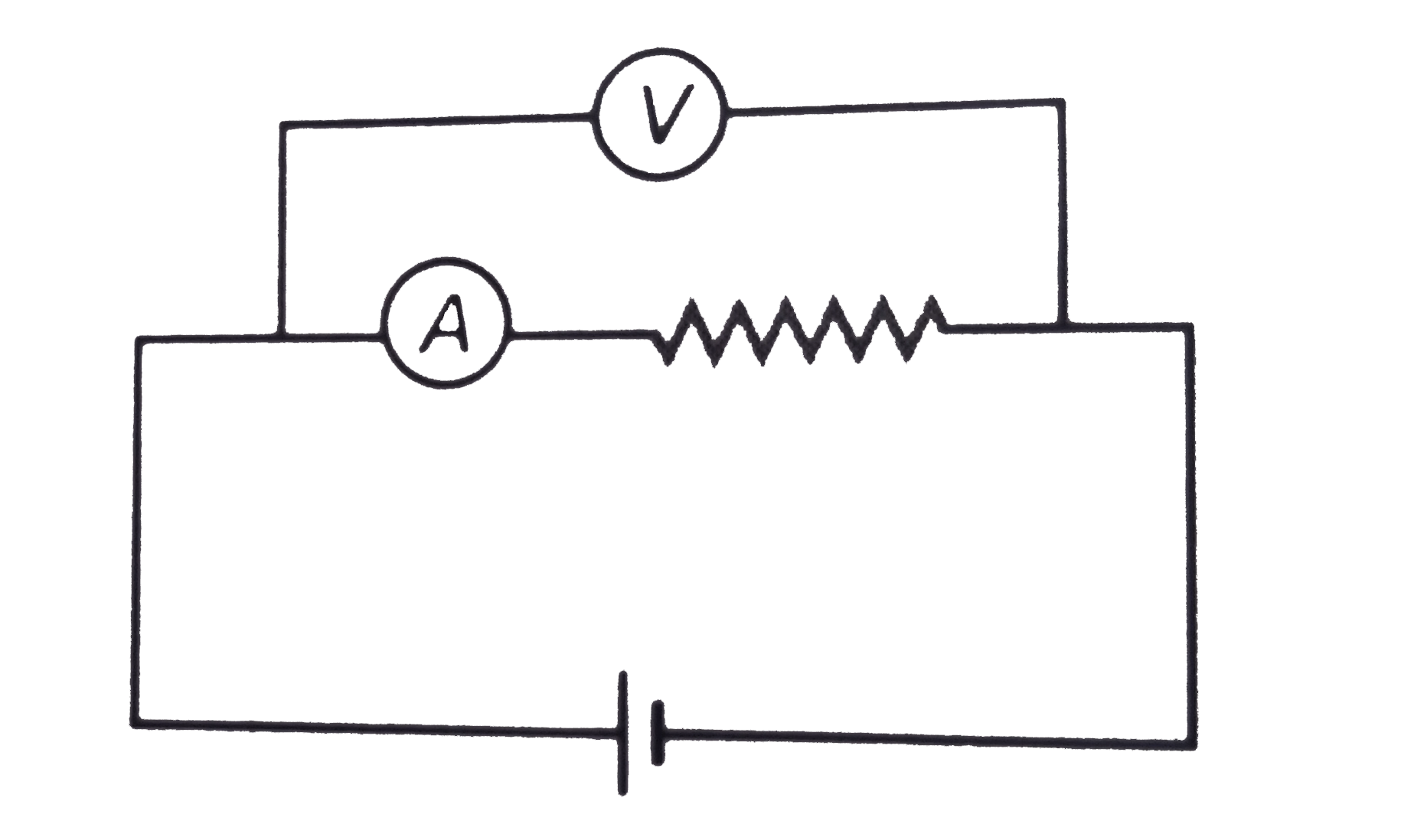
Assertion : In the circuit shown in figure ammeter and voltmeter are non-ideal. Why positions of ammeter and voltmeter are changed, reading of ammeter will increase while of voltmeter will decrease.
Reason : Resistance of an ideal ammeter is zero while that of an ideal voltmeter is infinite.AIf both Assertion and Reason are true and the Reason is correct explanation of the Assertion.BIf both Assertion and Reason are true but Reason is not the correct explanation of Assertion.CIf Assertion is true, but the Reason is false.DIf Assertion is false but the Reason is true.A circuit is shown in the figure. The ratio of readings of ideal voltmeter to reading of ideal ammeter is
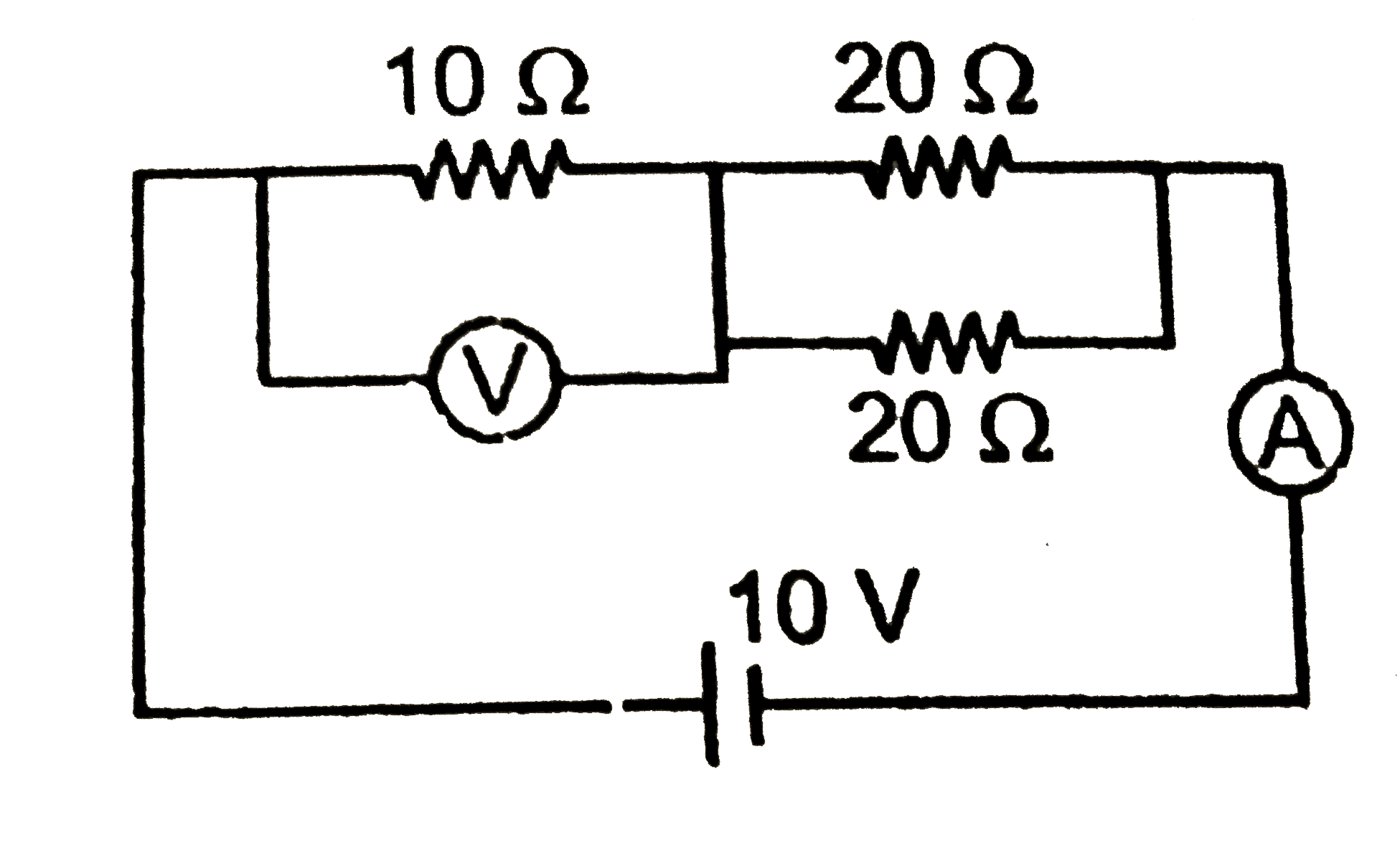 A5B0.5C10D2.5
The reading of ammeter in the circuit shown in the figure is
_PHY_E05_104_Q01.png)
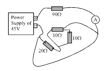
View SolutionWhat will the ideal ammeter reading for the circuit shown here ?
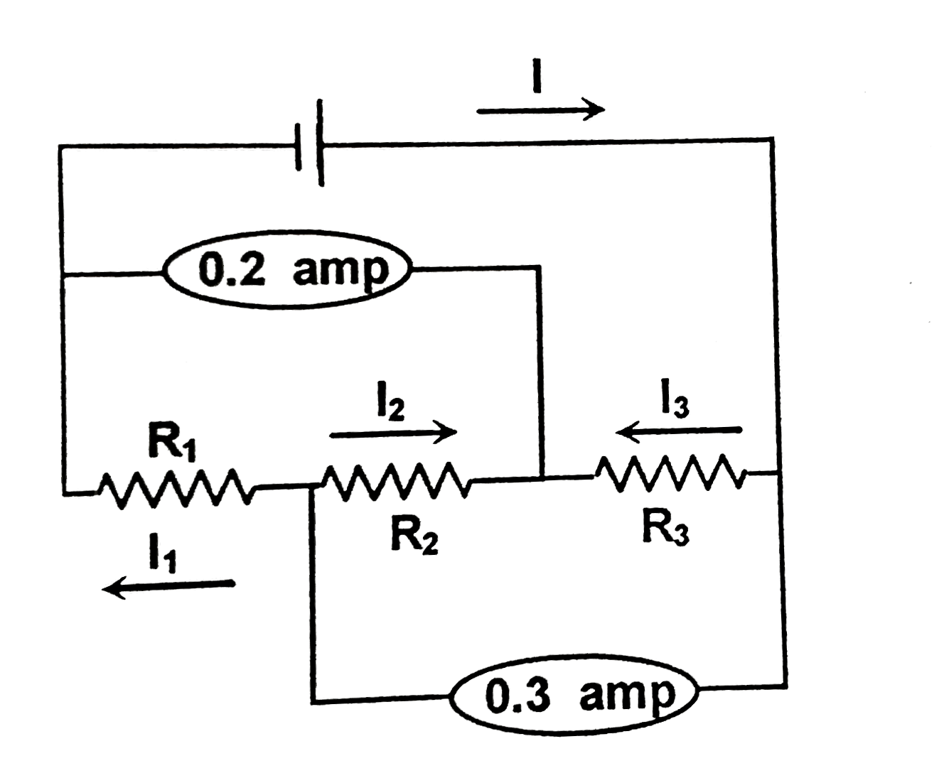
View SolutionA circuit contains an ideal battery, three resistors and two ideal ammeters. The ammeters read 0.2 amp and 0.3 amp. After two of the resistor are switched (inerchanged) the readings of ammeter do not change. Then
View SolutionIn the following circuit readings in ammeters A1 and A2 will be -
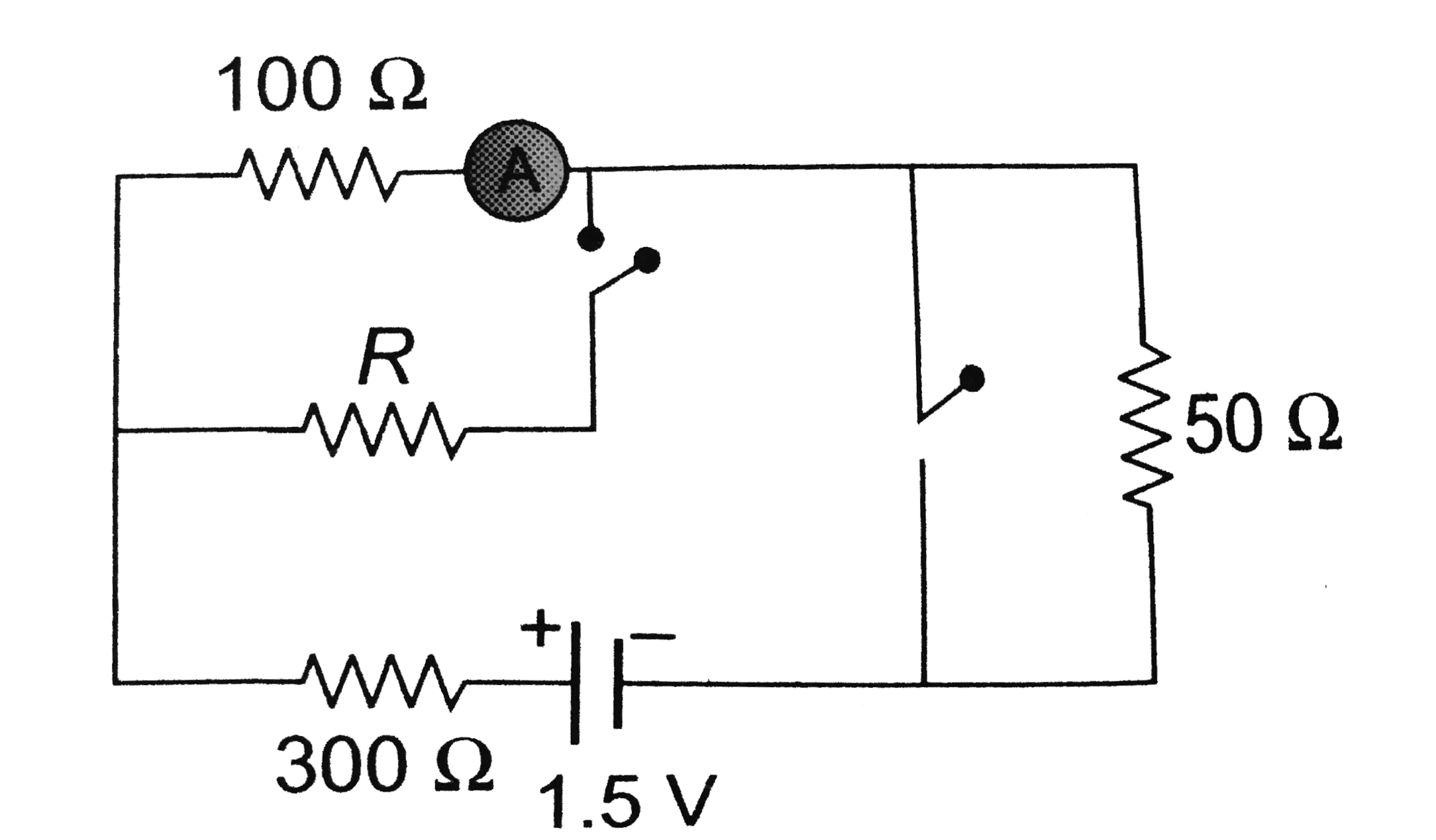
View SolutionIn the circuit shown in figure the reading of ammeter is the same with both switches open as with both closed. Then find the resistance R. (ammeter is ideal).
View Solution

