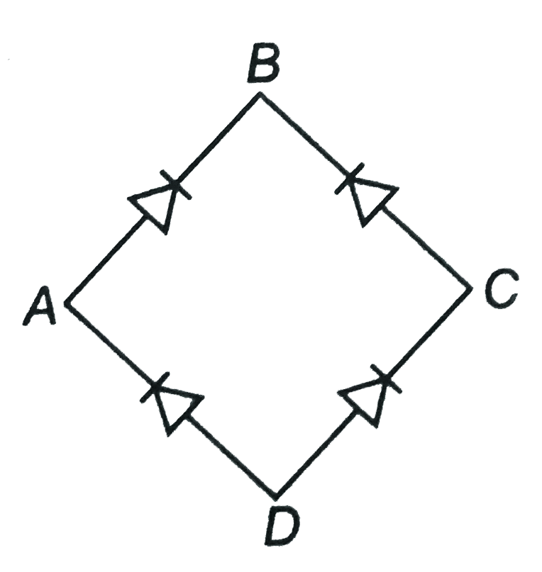
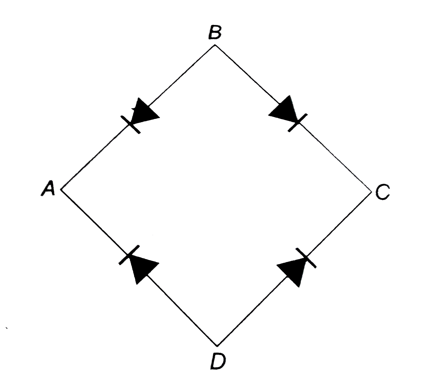
In the figure, the input is across the terminals
A and C and the output is across B and D. Then the output is
(a ) zero
( b) same as the input
( c) full - wave rectified
(d) half - wave rectified .
zero
same as input
full wave rectified
half wave rectified
The correct Answer is:C
Step by step video, text & image solution for In the figure, the input is across the terminals A and C and the output is across B and D. Then the output is (a ) zero ( b) same as the input ( c) full - wave rectified (d) half - wave rectified . by Physics experts to help you in doubts & scoring excellent marks in Class 11 exams.
Topper's Solved these Questions
- BOOK - ALLENCHAPTER - SEMICONDUCTORSEXERCISE - Part-3(Exercise-3)27videos
SEMICONDUCTORS
- BOOK - ALLENCHAPTER - SEMICONDUCTORSEXERCISE - Part-3(Exercise-4)51videos
SEMICONDUCTORS
- BOOK - ALLENCHAPTER - SEMICONDUCTORSEXERCISE - Part-3(Exercise-1)84videos
SEMICONDUCTORS
- BOOK - ALLENCHAPTER - PHYSICAL WORLD, UNITS AND DIMENSIONS & ERRORS IN MEASUREMENT EXERCISE - EXERCISE-IV8videos
PHYSICAL WORLD, UNITS AND DIMENSIONS & ERRORS IN MEASUREMENT
- BOOK - ALLENCHAPTER - WAVES AND OSCILLATIONSEXERCISE - Part-1(Exercise-05)[B]42videos
WAVES AND OSCILLATIONS
Similar Questions
Knowledge Check
- Question 1 - Select One
In Fig. the input is across the terminals A and C and the output is across B and D. Then the output is
 Ahalf wave rectifiedBfull wave rectifiedCzeroDsame as the input
 - Question 2 - Select One
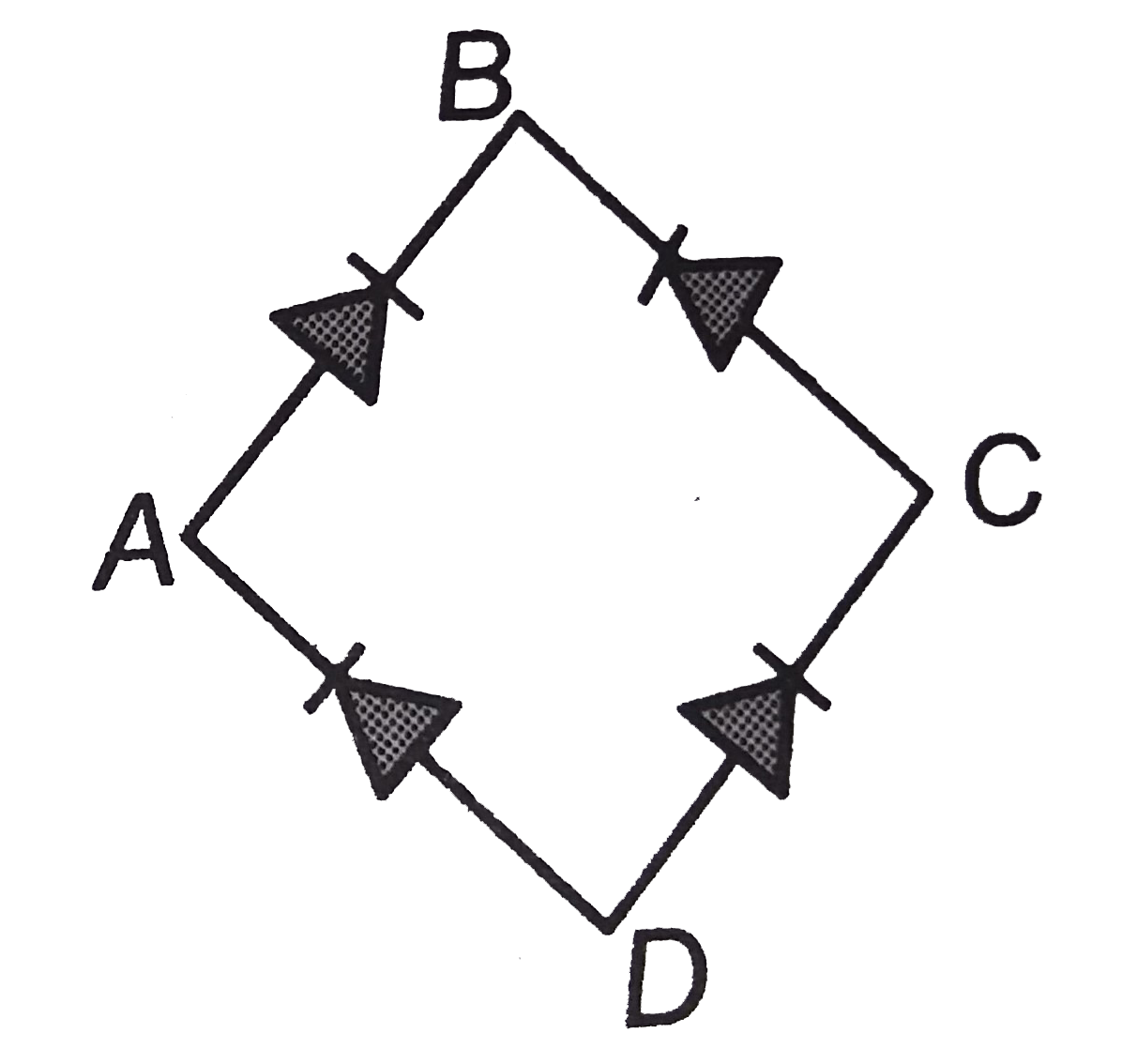
In the diagram, the input is across the terminals A and C and the output is across the terminals B and D, then the outputs is
 AzeroBsame as inputCFull wave rectifierDHalf wave rectifier
 - Question 3 - Select One
The output form of full-wave rectifier is
AAn AC voltageBA DC voltageCZeroDA pulsating unidirectional voltage
Give any two differences between a half-wave rectifier and a full-wave rectifier.
View SolutionGive any two difference between a half wave rectifier and a full wave rectifier.
View SolutionA bridge rectifier is shown in figure. Alternating input is given across A and C. If output is taken across BD, then it is
 View Solution
If the input frequency of half-wave rectifier is nHzac, then its output is
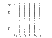
View SolutionThe figure shows the voltage waveforms across two inputs A and B and the output Y of a logic circuit. The logic circuit gate is
 View Solution


