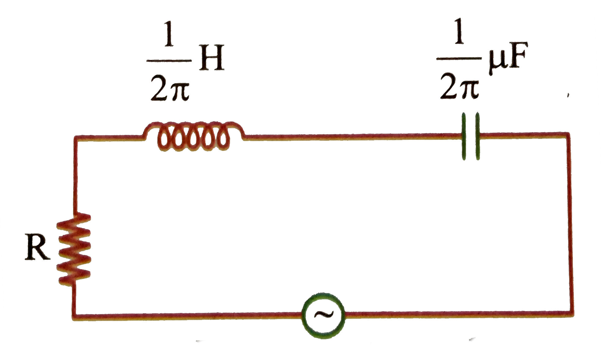
An alternating EMF of frequency 12π√LC is applied to a series LCR circuit. For this frequency of the applied EMF,
The circuit is at resonance and its impedance is made up only of a reactive part
The current in the circuit is not in phase with the applied e.m.f. and the voltage across R equals this applied emf
The sum of the p.d.’s across the inductance and capacitance equals the applied e.m.f. which is 180∘ ahead of phase of the current in the circui
The quality factor of the circuit isωL/R or 1/ωCRand this is a measure of the voltage magnification (produced by the circuit at resonance) as well as the sharpness of resonance of the circuit
Step by step video & image solution for An alternating EMF of frequency (1)/(2pi sqrt(LC)) is applied to a series LCR circuit. For this frequency of the applied EMF, by Physics experts to help you in doubts & scoring excellent marks in Class 12 exams.
Topper's Solved these Questions
Similar Questions
An alternating voltage of frequency f is applied across a series LCR circuit.Le fr be the resonance frequency for the circuit.Will the current in the circuit lag, lead or remain in phase with the applied voltage when (i)f>fr,(ii)f<fr ? Explain your answer in each case.
View SolutionResonance occures in a series LCR circuit when the frequency of the applied emf is 1000 Hz.
View Solution
Knowledge Check
- Question 1 - Select One
In a series LCR circuit, at resonant frequency.
Athe impedance and the current are maximumBthe impedance is maximumCthe current and voltage are maximumDthe current and voltage are minimum - Question 2 - Select One
In a series LCR circuit
 Athe current leads on the emf by π/2 radBthe current lags on the emf by π/2 radCthe current leads on the emf only if the circuit behaves inductivelyDthe current leads on the emf only if the circuit behaves capacitively.
 - Question 3 - Select One
An alternating e.m.f. is applied to a series L-C-R circuit. If the frequency of the applied e.m.f. is more than the resonant frequency of the circuit then the circuit will act as
Aa resistive circuitBan indcutive circuitCa capacitive circuitDan oscillatory circuit
An alternating e.m.f. of 100V (rms) is applied to a series LCR circuit. At resonance, the potential difference across the inductance and across the capacitance is 400V each. The potential difference across the resistance will be
View SolutionAt resonant frequency the current amplitude in series LCR circuit is
View SolutionA capacitor of capacitance 2 μF and resistance of 100 Ω are connected in series and an alternating emf of frequency 1 kHz is applied across the combination. The phase difference between applied emf and current is nearly
View SolutionIn an LCR. series circuit the resonating frequency can be decreased by -
View SolutionAn AC source of variable frequency is applied across a series L−C−R circuit. At a requency double the resonace frequency. The impedance is √10 times the minimum impedance. . The inductive reactance is
View Solution

