In Fig. shown, the rod has a resistance R, the horizontal rails have negligible friction. A battery of emf E and negligible internal resistance is connected between points aandb. The rod is released from rest.
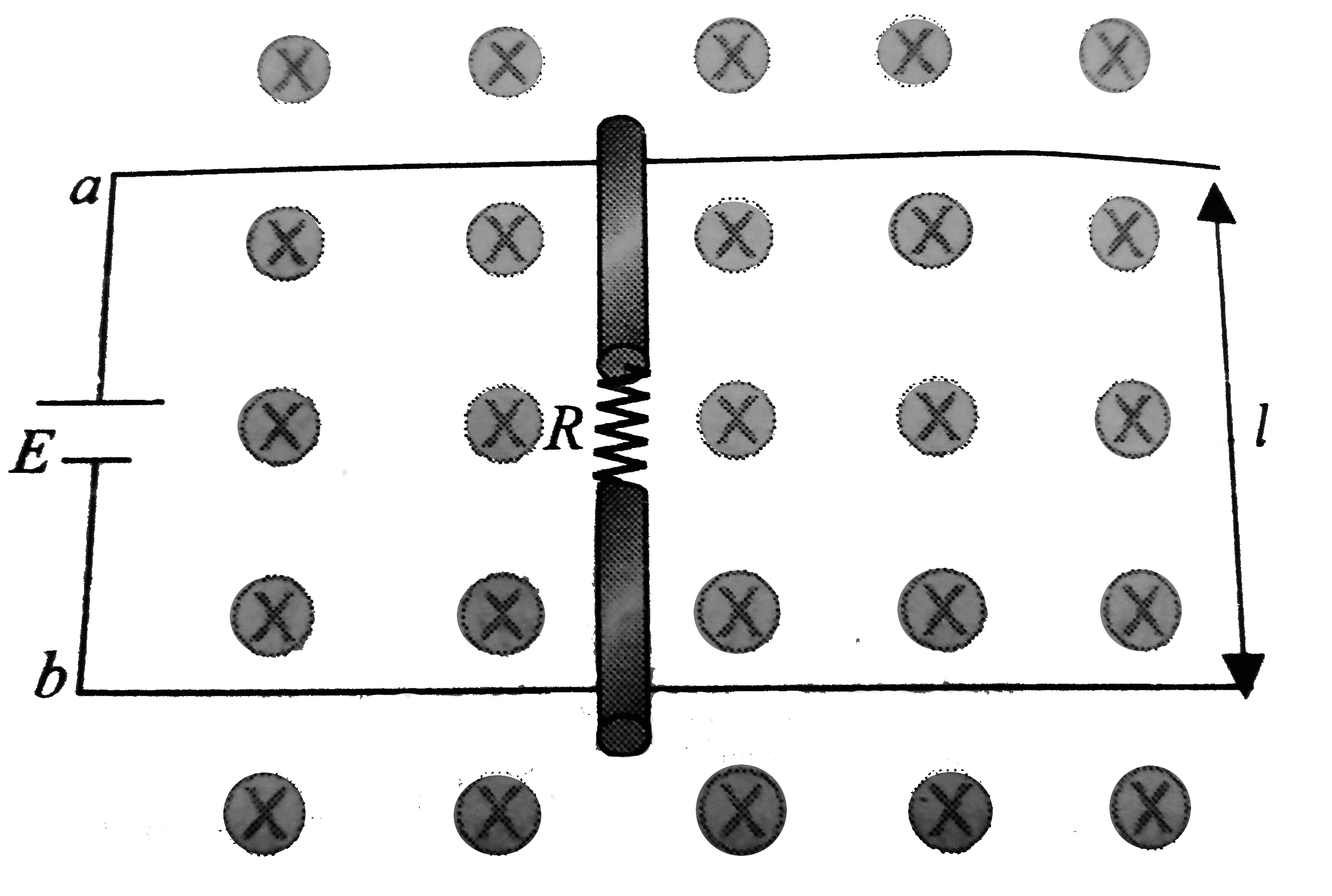
The current when the rod attains its terminal speed is
2ER
ER
32ER
zero
Step by step video & image solution for In Fig. shown, the rod has a resistance R, the horizontal rails have negligible friction. A battery of emf E and negligible internal resistance is connected between points a and b. The rod is released from rest. The current when the rod attains its terminal speed is by Physics experts to help you in doubts & scoring excellent marks in Class 12 exams.
Updated on:21/07/2023Topper's Solved these Questions
Similar Questions
A 5 V battery of negligible internal resistance is connected across a 200 V battery and a resistance of 39Ω as shown in the figure. Find the value of the current.

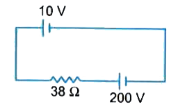
View SolutionA 10 V battery of negligible internal resistance is connected across a 200 V battery and a resistance of 38 Ω as shown in the Fig. Find the value of the current in circuit.
View Solution
Knowledge Check
In Fig. shown, the rod has a resistance R, the horizontal rails have negligible friction. A battery of emf E and negligible internal resistance is connected between points aandb. The rod is released from rest.
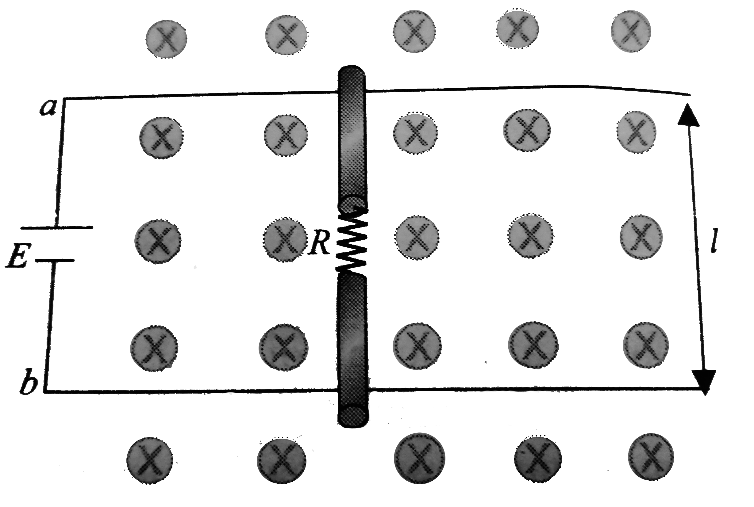
The velocity of the rod as function of time isA(a) EBl(1−e−t/τ)B(b) EBl(1+e−t/τ)C( c) 32EBl(1−e−t/τ)D(d) E2Bl(1−e−t/τ)In Fig. shown, the rod has a resistance R, the horizontal rails have negligible friction. A battery of emf E and negligible internal resistance is connected between points aandb. The rod is released from rest.
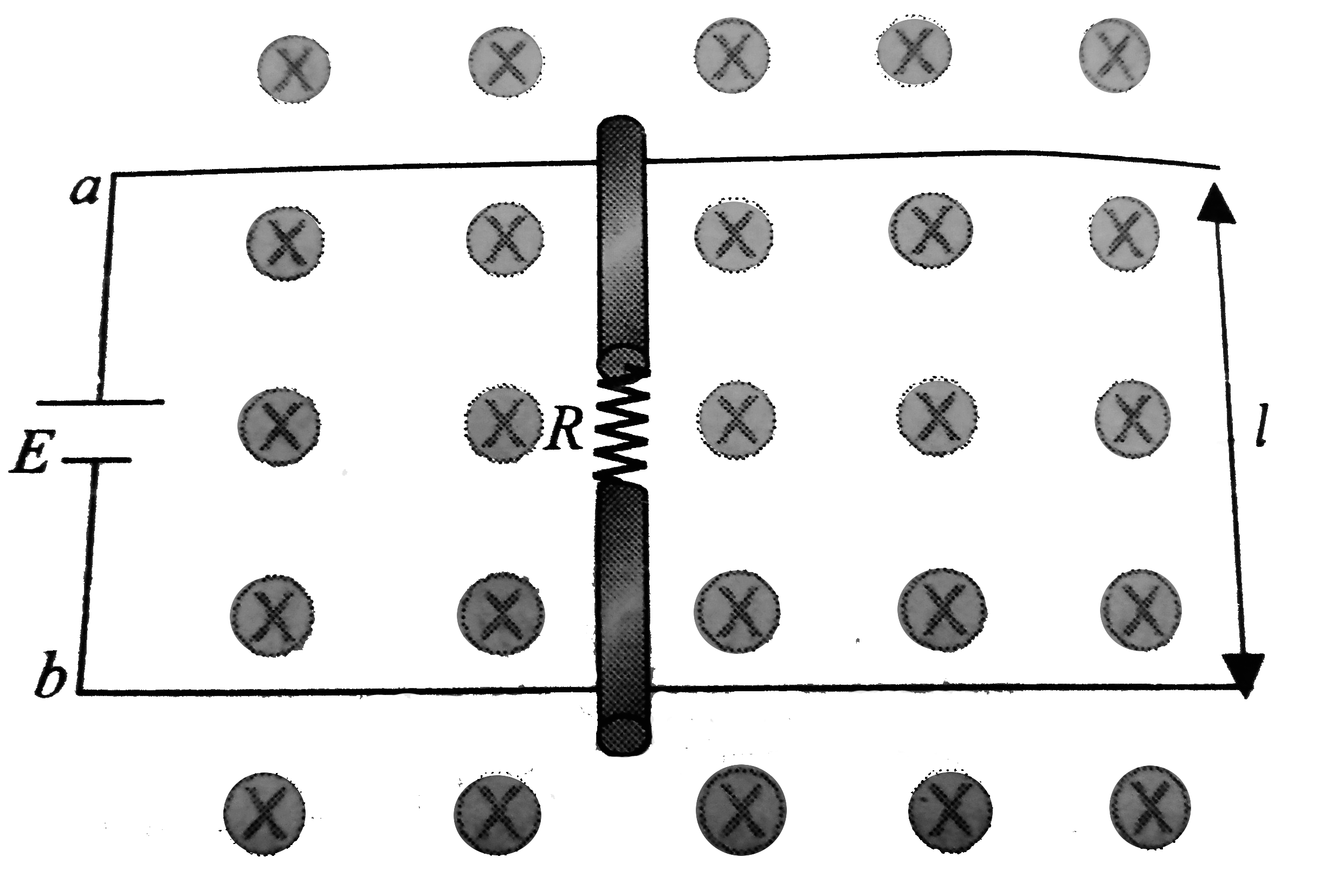
after some time, the rod will approach a terminal speed . Find an expression for it.A32EBlBE2BlCEBlD2EBlA 3 volt battery with negligible internal resistance is connected in a circuit as shown in the figure. The current I, in the circuit will be
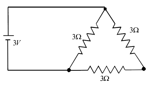 A1AB1.5AC2AD1/3A
Two identical cells, each of emf ε , having negligible internal resistance, are connected in parallel with each other across an external resistance R. What is the current through this resistance ?
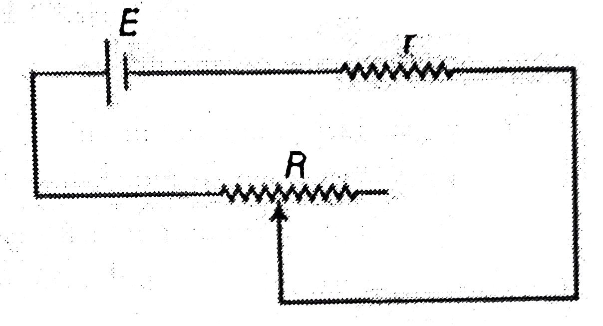
View SolutionA battery of emf E and internal resistance r is connected to a variable resistor R as shown in figure. Which one of the following is true ?
View SolutionA conducting wire of uniform cross section, having resistance R is bent to form a circle. O is the centre of this circle. Two points P and Q are selected on the ring in such a manner that ∠POQ is θ. If a battery of emf E and negligible internal resistance is connected between P and Q, then the current drawn from the battery would be
View SolutionA series combination of L and R is connected to a battery of emf E having negligible internal resistance. The final value of current depeds upon
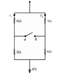
View SolutionIn the figure, the point at the top is at 36 volts and the bottom point is at 0V. In other words, there is a battery of 36V emf and negligible internal resistance between these points. What is the current through the switch S when it is closed?
View Solution