Which of the following figure correctly depicts the Lenz’s law. The arrows show the movement of the labelled pole of a bar magnet into a closed circular loop and the arrows on the circle show the direction of the induced current
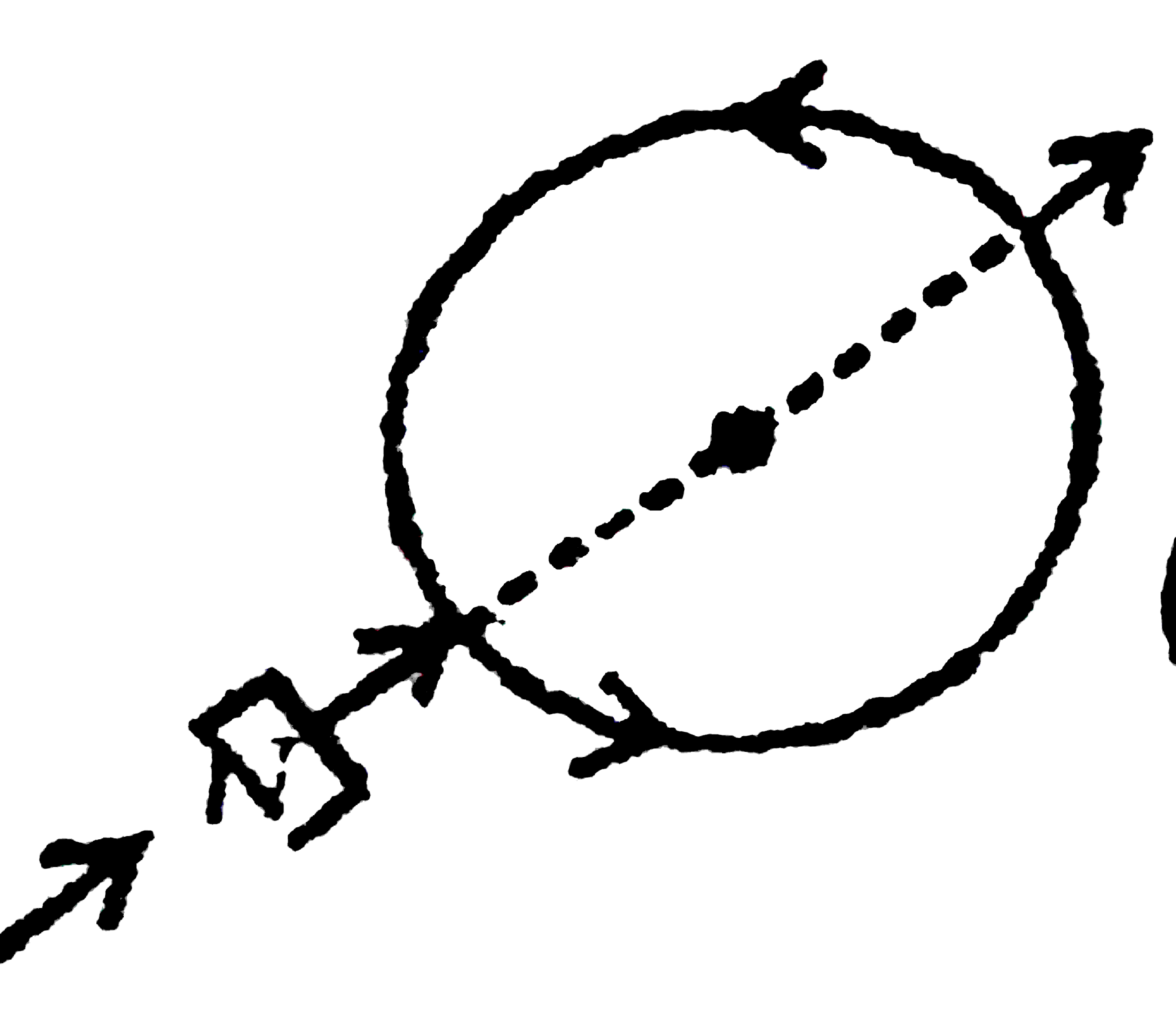
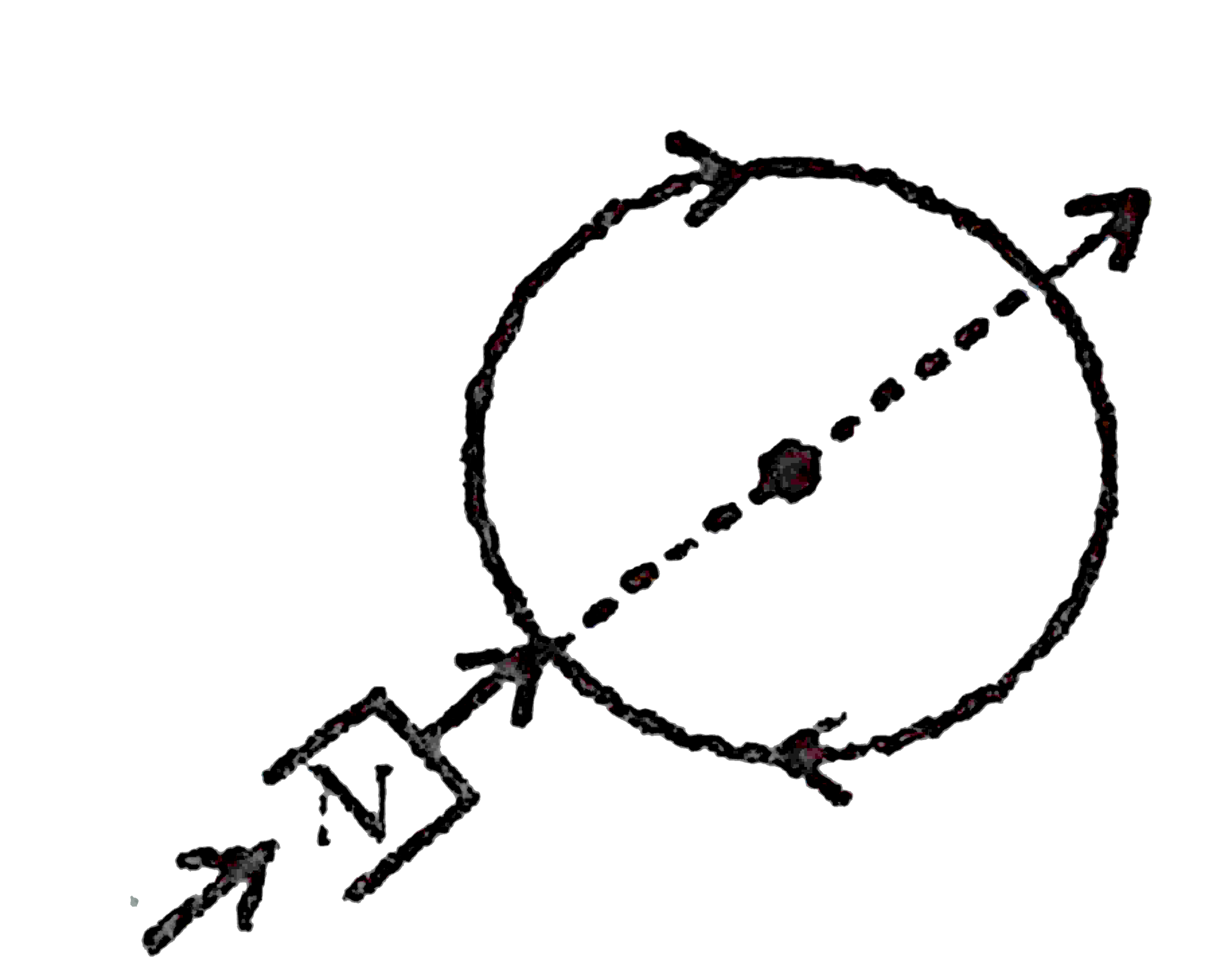
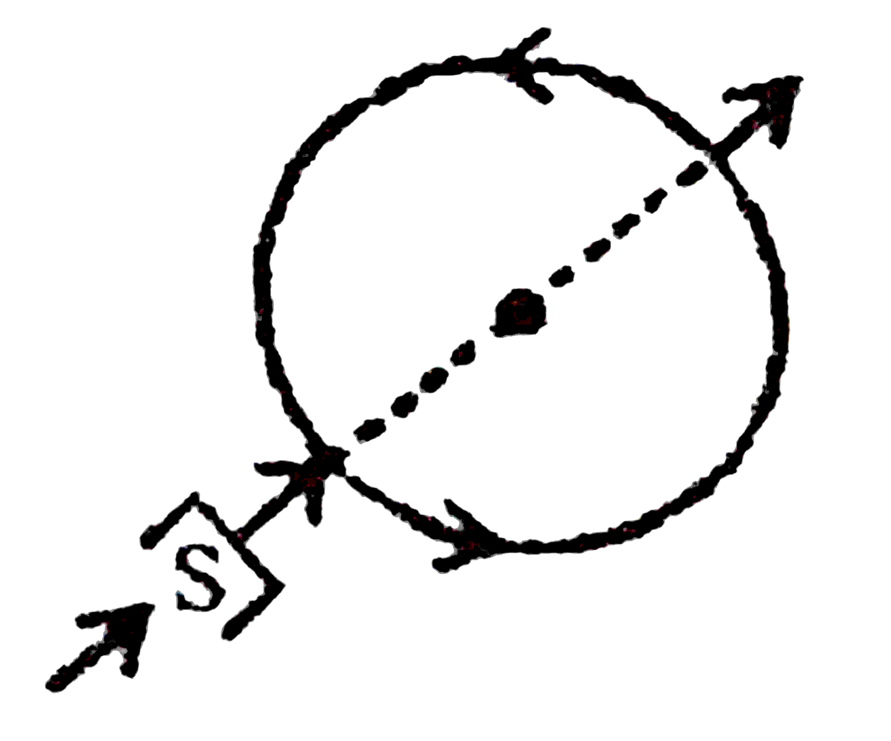
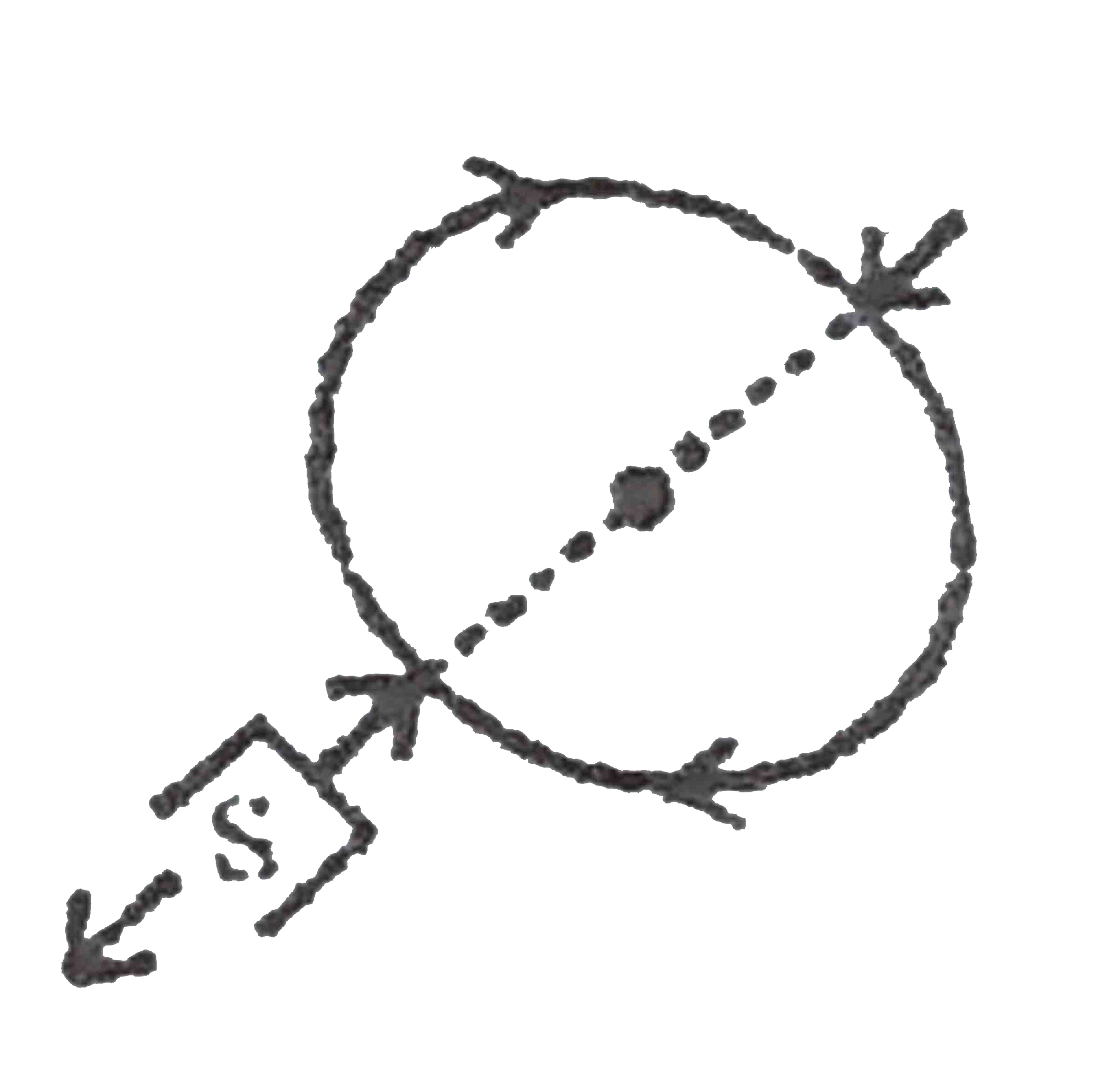
Step by step video & image solution for Which of the following figure correctly depicts the Lenz’s law. The arrows show the movement of the labelled pole of a bar magnet into a closed circular loop and the arrows on the circle show the direction of the induced current by Physics experts to help you in doubts & scoring excellent marks in Class 11 exams.
Topper's Solved these Questions
Similar Questions
A bar magnet is moved in the direction indicated by the arrow between two coil PQ and CD. Predict the directions of induced current in each coil.
 View Solution
Write the possible structures for the following molecules .Show the direction of the movement of electrons with the help of arrows.
 View Solution
Knowledge Check
- Question 1 - Select One
An electron moves along the line PQ which lies in the same plane as a circular wire as shown in figure. What will be the direction of the induced current in the loop ?
 AAnticlockwiseBClockwiseCAlternatingDNo current will be induced
 - Question 2 - Select One
An electron moves along the line PQ which lies in the same plane as a circular wire as shown in figure. What will be the direction of the induced current in the loop ?
 AAnticlockwiseBClockwiseCAlternatingDNo current will be induced
 - Question 3 - Select One
A bar magnet with its north (N) and south (S) poles as shown in the following figure is initially moving to the left, along the axis of, and away from a circular conducting loop. A current l is induced in the loop, with a being the acceleration of the magnet due to this current. As seen from the magnet looking in the direction of the loop,
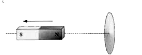 AI runs clockwise and a points to the leftBI runs counterclockwise and a points to the rightCI runs clockwise and a points to the rightDI runs counterclockwise and a points to the left
Write the possible structures for the following molecules .Show the direction of the movement of electrons with the help of arrows.
 View Solution
Write the possible structures for the following molecules .Show the direction of the movement of electrons with the help of arrows.
 View Solution
Write the possible structures for the following molecules .Show the direction of the movement of electrons with the help of arrows.
 View Solution
A closed conducting ring is placed in between two bar magnets as shown in the figure. The pole strenght of M1 is double that of M2. When the two bar magnets are at same distance from the centre of the ring, the bar magnet M1 has given a velocity 2v while M2 is given velocity v in the direction as shown in the figure.
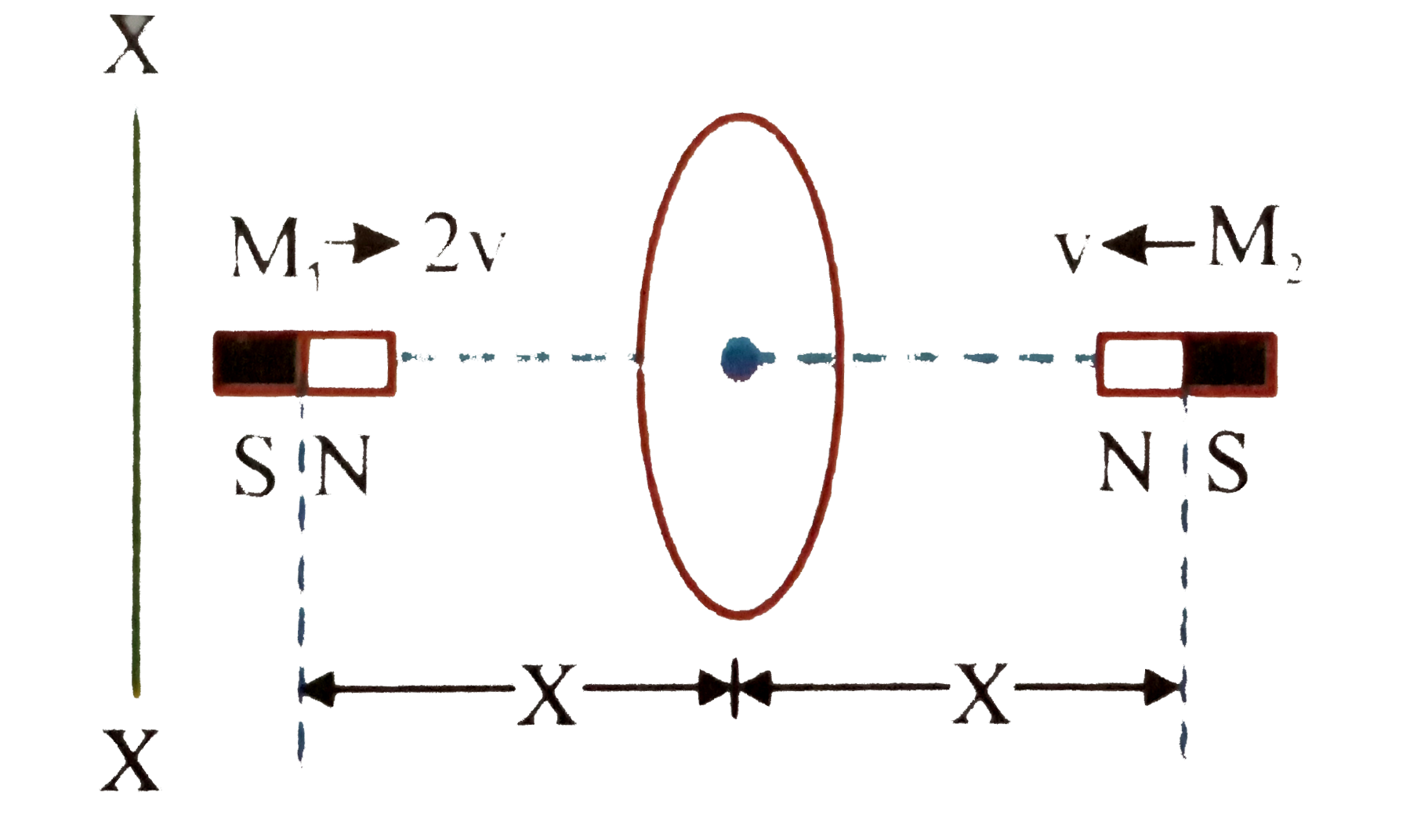
The direction of induced current in the ring as seen from XX from this moment to the moment till bar magnets collide isView SolutionA closed conducting ring is placed in between two bar magnets as shown in the figure. The pole strength of M1 is double that of M2 . When the two bar magnets are at same distance from the centre of the ring, the bar magnet M1 has given a velocity 2v while M2 is given velocity v in the direction as shown in the figure.
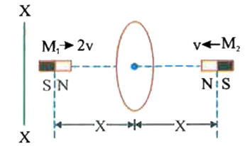
The direction of induced current in the ring as seen from XX from this moment to the moment till bar magnets collide isView Solution

