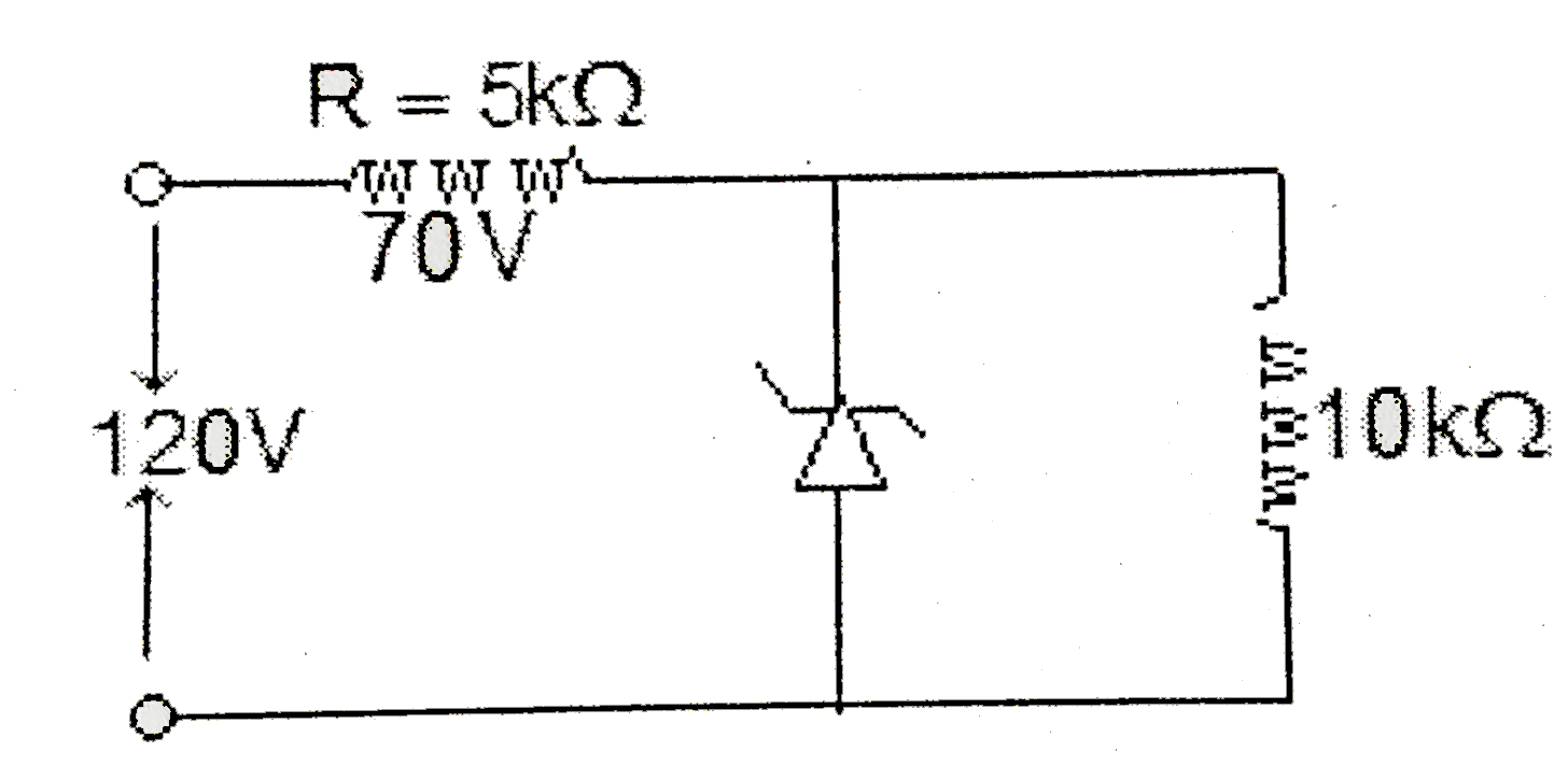
For the circuit shown in the figure:
A
current through zener diode is 4 mA.
B
current through zener diode is 9 mA
C
the output voltage is 50 V
D
the output voltage is 40 V
Video Solution
Text Solution
The correct Answer is:B, C
|
Answer
Step by step video, text & image solution for For the circuit shown in the figure: by Physics experts to help you in doubts & scoring excellent marks in Class 12 exams.
Updated on:21/07/2023
Topper's Solved these Questions
- BOOK - BANSALCHAPTER - SEMICONDUCTORSEXERCISE - Exercise-324videos
SEMICONDUCTORS
- BOOK - BANSALCHAPTER - SEMICONDUCTORSEXERCISE - Exercise-437videos
SEMICONDUCTORS
- BOOK - BANSALCHAPTER - SEMICONDUCTORSEXERCISE - CBSE Question32videos
SEMICONDUCTORS
- BOOK - BANSALCHAPTER - MASTER PRACTICE PROBLEMEXERCISE - Additional topic70videos
MASTER PRACTICE PROBLEM
- BOOK - BANSALCHAPTER - TEST PAPERSEXERCISE - PHYSICS PART C14videos
TEST PAPERS
Similar Questions
Knowledge Check
- Question 1 - Select One
Find the equivalent capacitance between P and Q in the circuit shown in the figure:
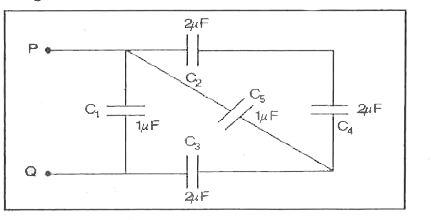 A2μFB4μFC6μFD3μF
 - Question 2 - Select One or More
In the circuit shown in the figure,
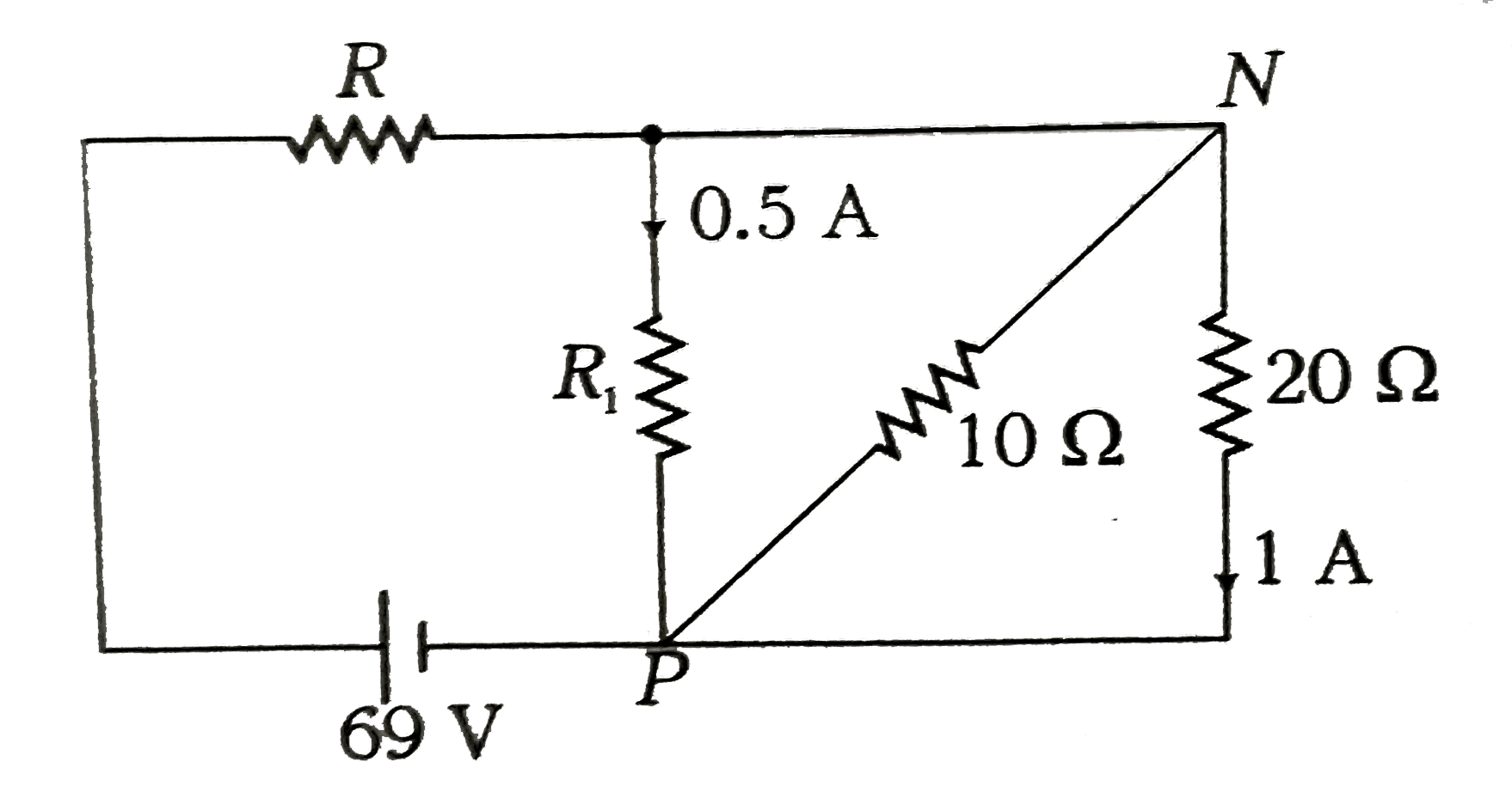 AThe current through NP is 0.5 ABThe value of R1=40ΩCThe value of R =14ΩDsThe potential difference across R = 49 V
 - Question 3 - Select One or More
In the circuit shown in the figure
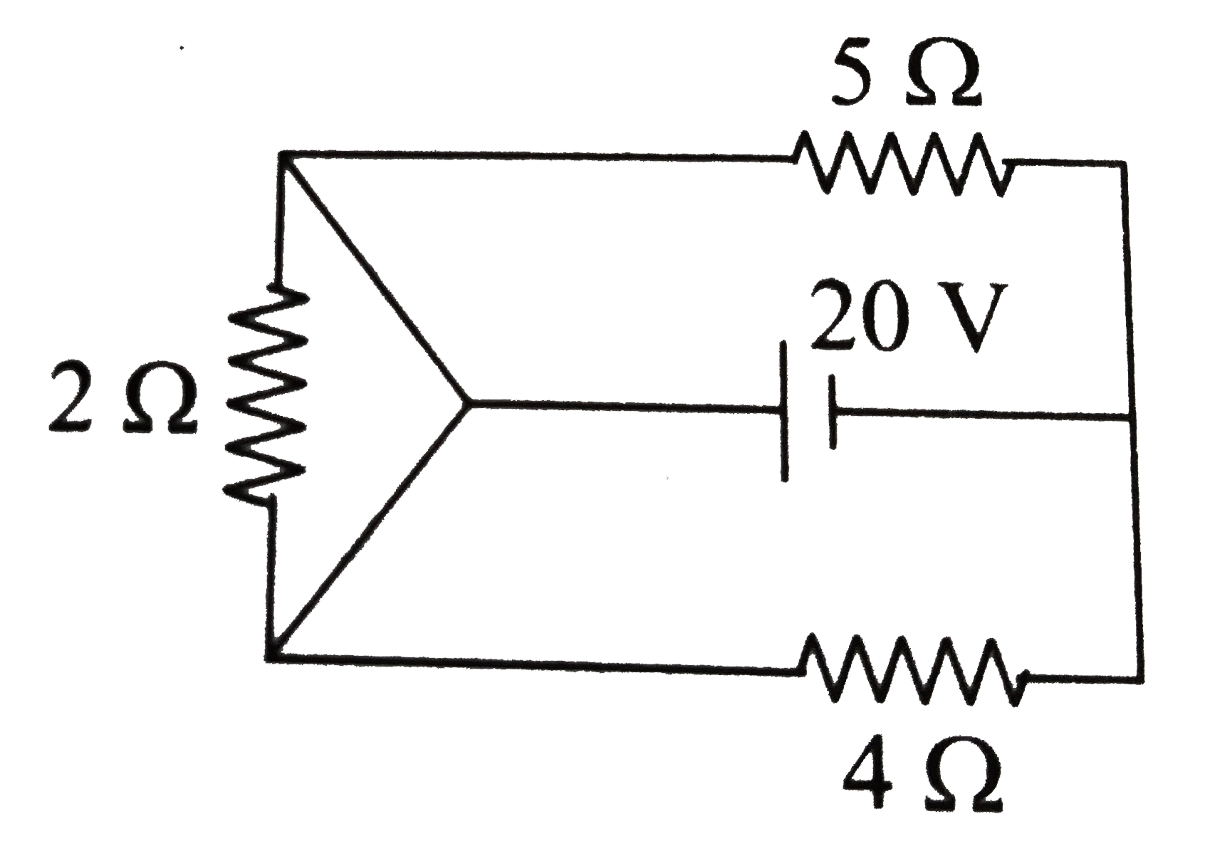 . Acurrent passing through 2Ω resistance is zero.Bcurrent passing through 4Ω resistance is 5ACcurrent passing through 5Ω resistance is 4A.Dpotential difference across 2Ω resistance is zero.
The time constant of the circuit shown in the figure is
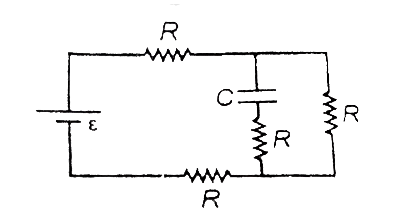 View Solution
The equivalent resistance of the circuit shown in the figure is
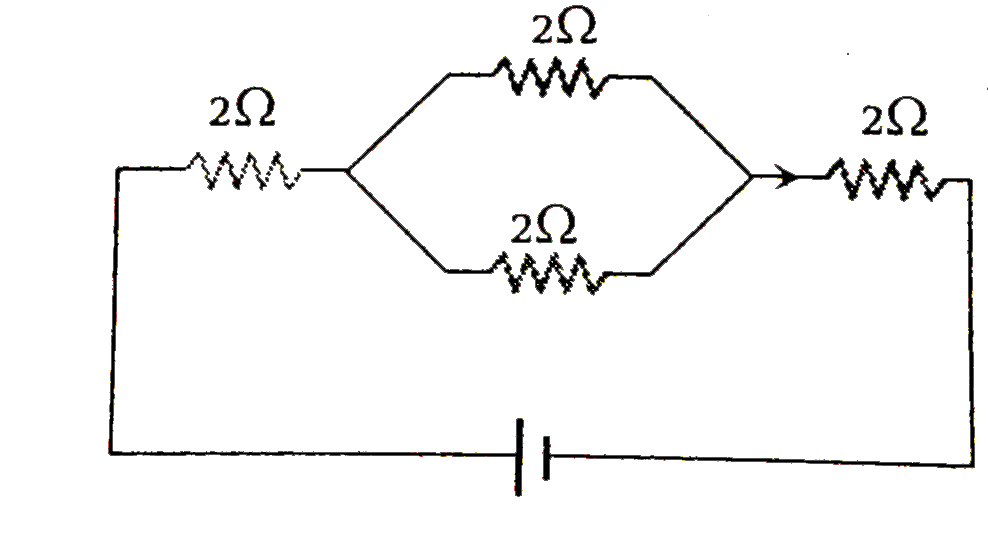 View Solution
The value of R in the circuit shown in the figure is
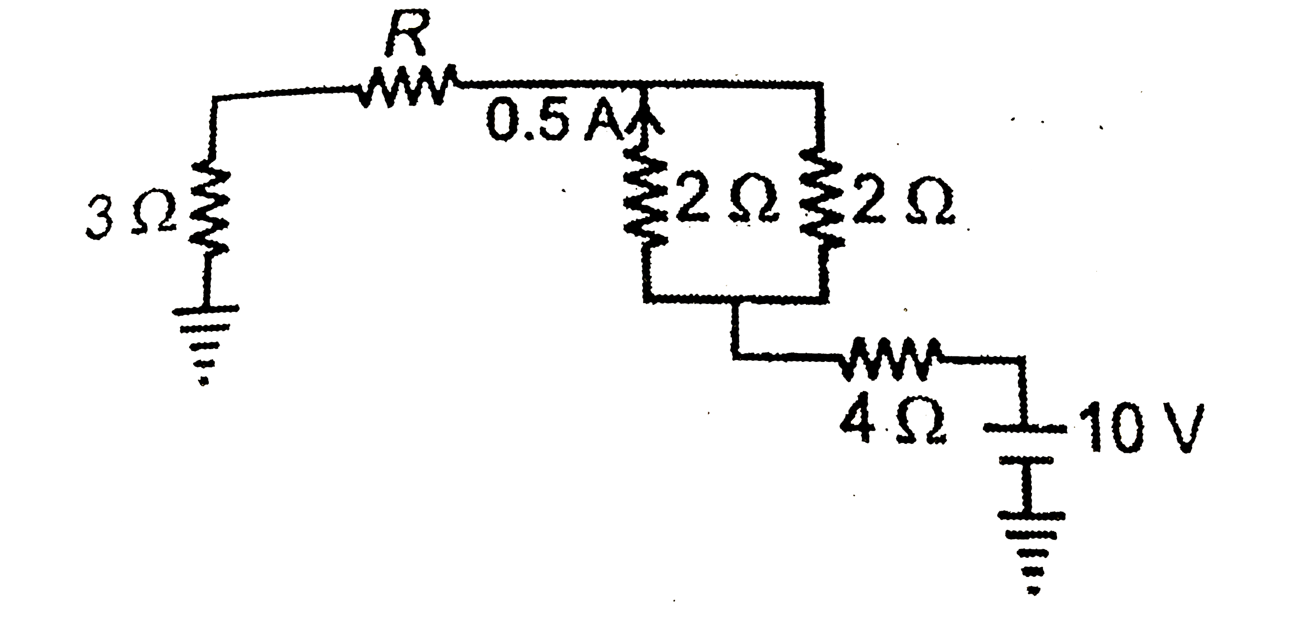 View Solution
The time constant of the circuit shown in the figure is
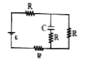 View Solution
The equivalent capacitance CAB of the circuit shown in the figure is.
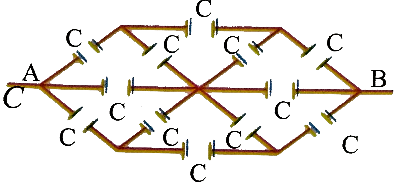 .View Solution


