In the circuit shown in figure, switch S is initially closed and S is open. Find V-V
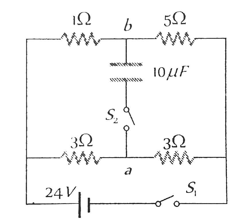
4V
8V
12V
16V
The correct Answer is:B
Step by step video, text & image solution for In the circuit shown in figure, switch S is initially closed and S is open. Find V-V by Physics experts to help you in doubts & scoring excellent marks in Class 12 exams.
Updated on:21/07/2023Topper's Solved these Questions
Similar Questions
In the circuit shown in figure find Vab at 1s

View SolutionCalculate the charge on each capacitor and the potential difference across it in the circuits shown in figure for the cases :
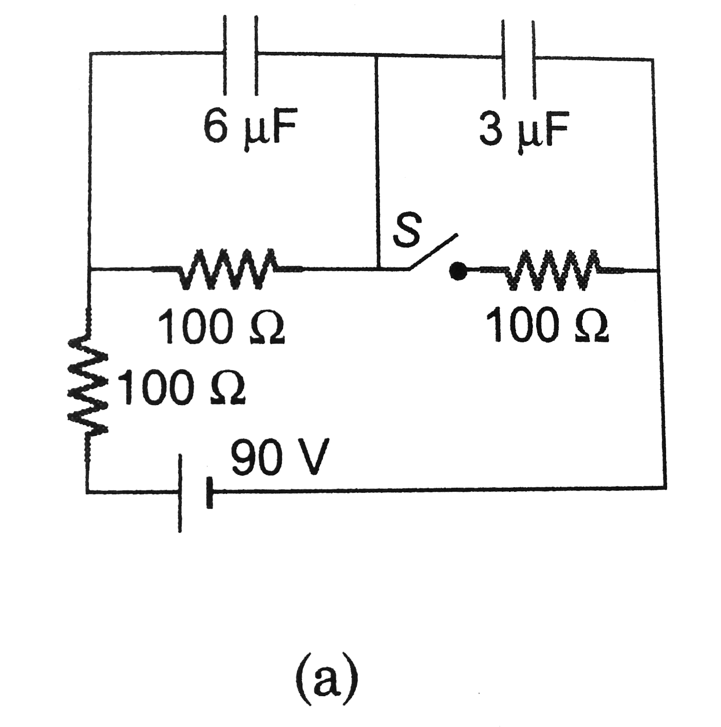
(i) switch S is closed and
(ii) switch S is open.
(iii) In. figure (b), what is the potential of point A when S is open?
View Solution
Knowledge Check
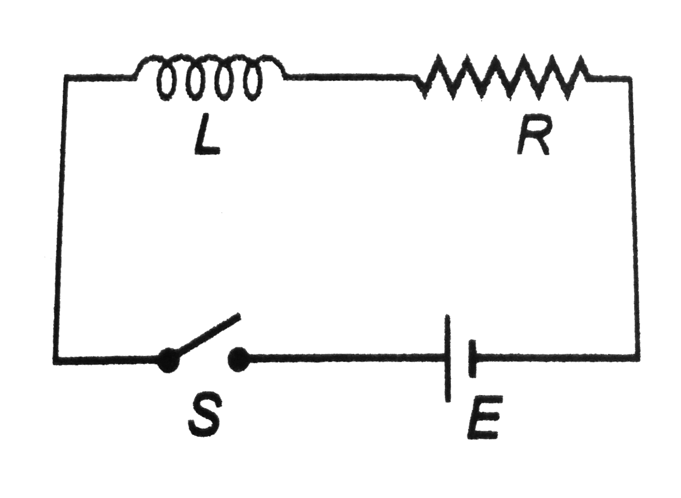
In the circuit shown in figure, the switch S is closed at t=0. If VL is the voltge induced across the inductor and i is the instantaneous current, the correct variation of VL versus is given by
 A
A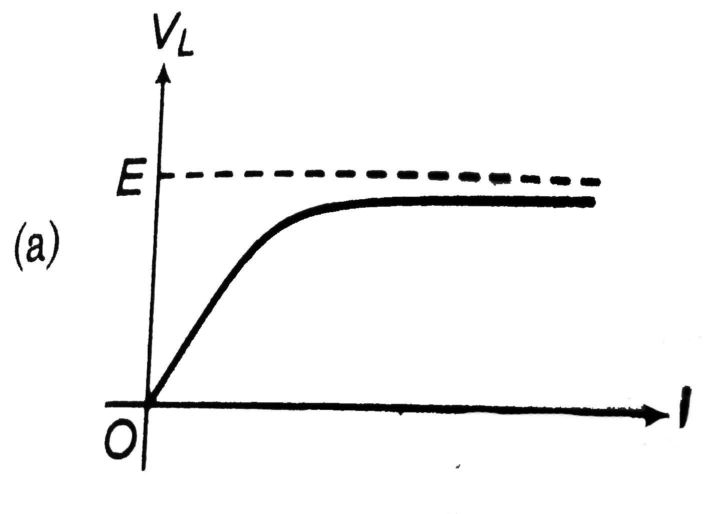 B
B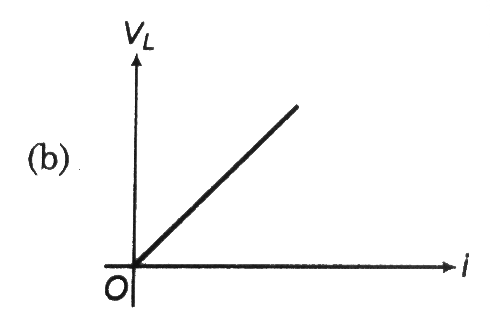 C
C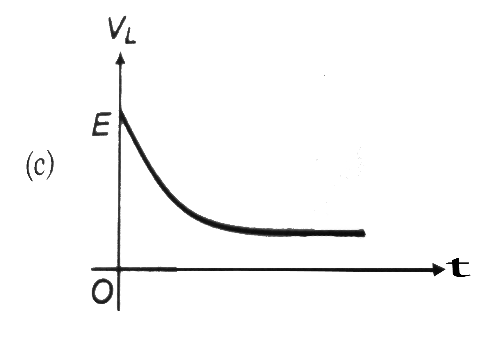 D
D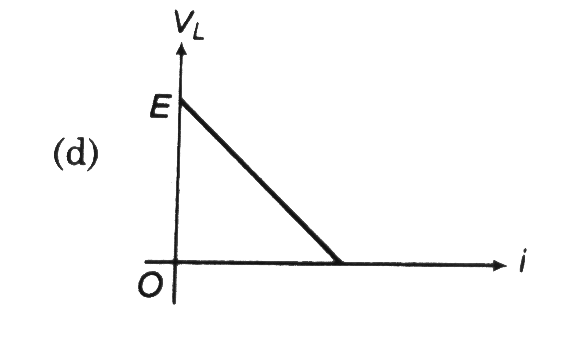
In the circuit shown, when switch S1 is closed and S2 is open, the ideal voltmeter shows a reaiding of 18V. When switch S2 is closed and S1 is open, the reading of voltmeter is 24V. When S1 and S2 both are closed, the voltmeter reading will be
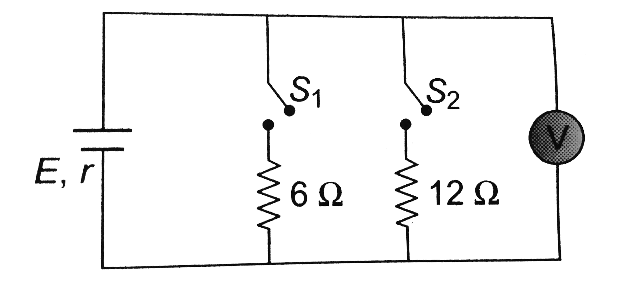 A14.4VB20.6VC24.4VD10.8V
In the circuit diagram shown in figure, initially switch S is opened and the circuit is in steady state. At time t=0, the switch S is closed and the new steady state is reached after some time. Choose the correct option(s)
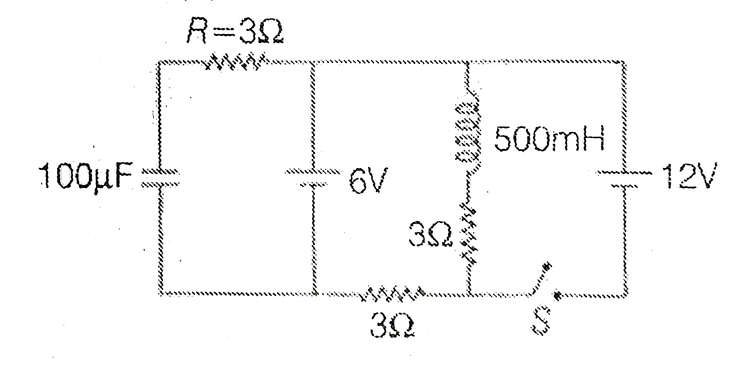 ACurrent in the indcutor when the circuit reaches the new steady state is 4A.BThe net change in the magnitic flux is the inductor is 1.5WbCThe net change in the magnetic flux in the conductor is 9volt when the circuit reaches the new steady state.DThe charge stored in the capacitor in the new steady state is 1.2mC
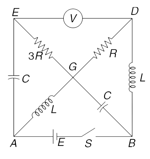
In the circuit shown, switch S is kept closed and the circuit is in steady state.
(a) Find reading of the ideal voltmeter
(b) Now the switch is opened. Find the reading of the voltmeter immedi- ately after the switch is opened.
(c) Fid the heat dissipated in resistance R after the switch is opened.
View Solution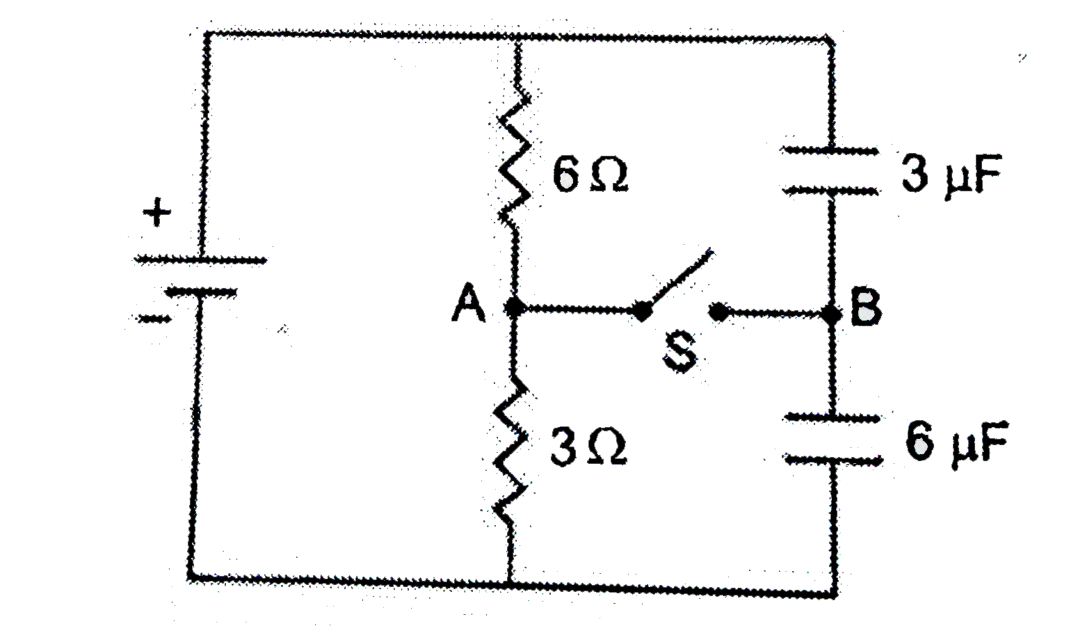
In the circuit shown above, when then switch S is closed,
View SolutionIn the circuit as shown in figure the switch is closed at t=0.
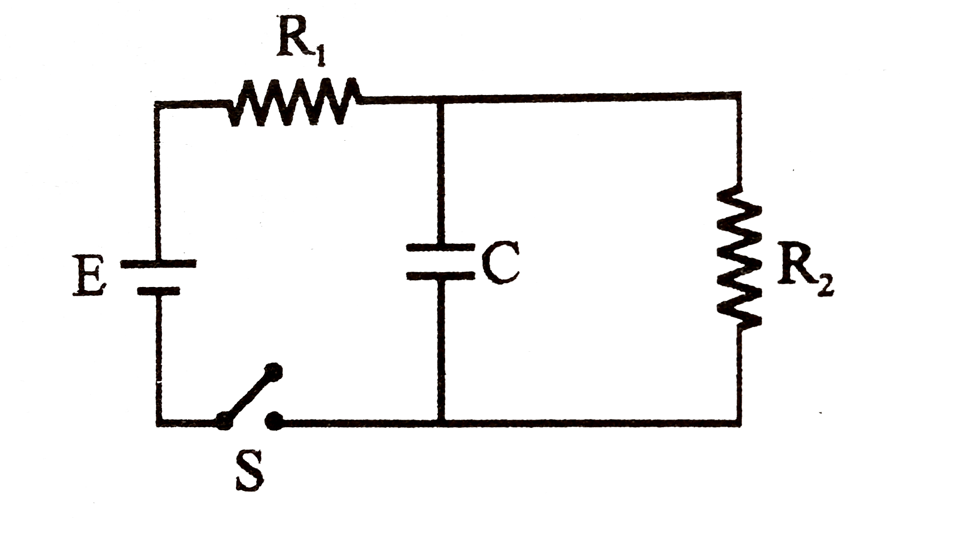
At the instant of closing the switch
View SolutionIn the circuit shown in figure initially the switch is opened. The switch is closed now.
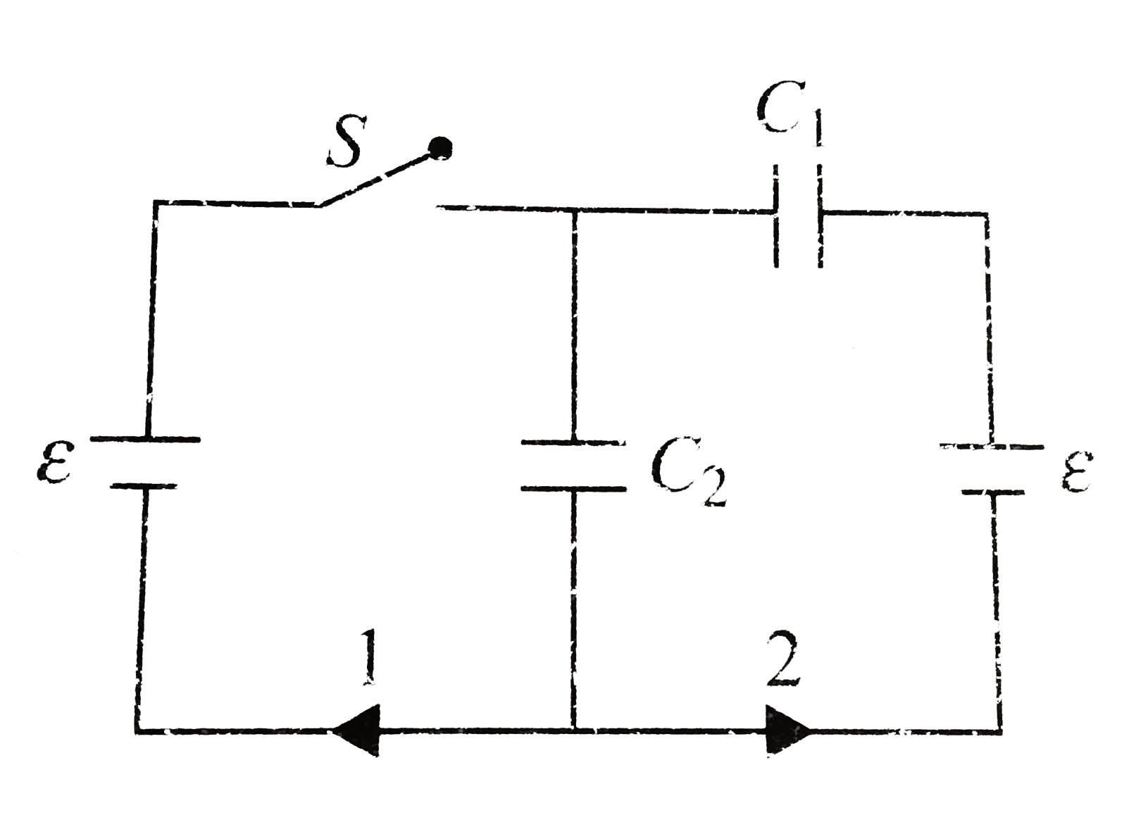
The charge that will flow in direction 1 is
View SolutionIn the circuit shown in figure initially the switch is opened. The switch is closed now.
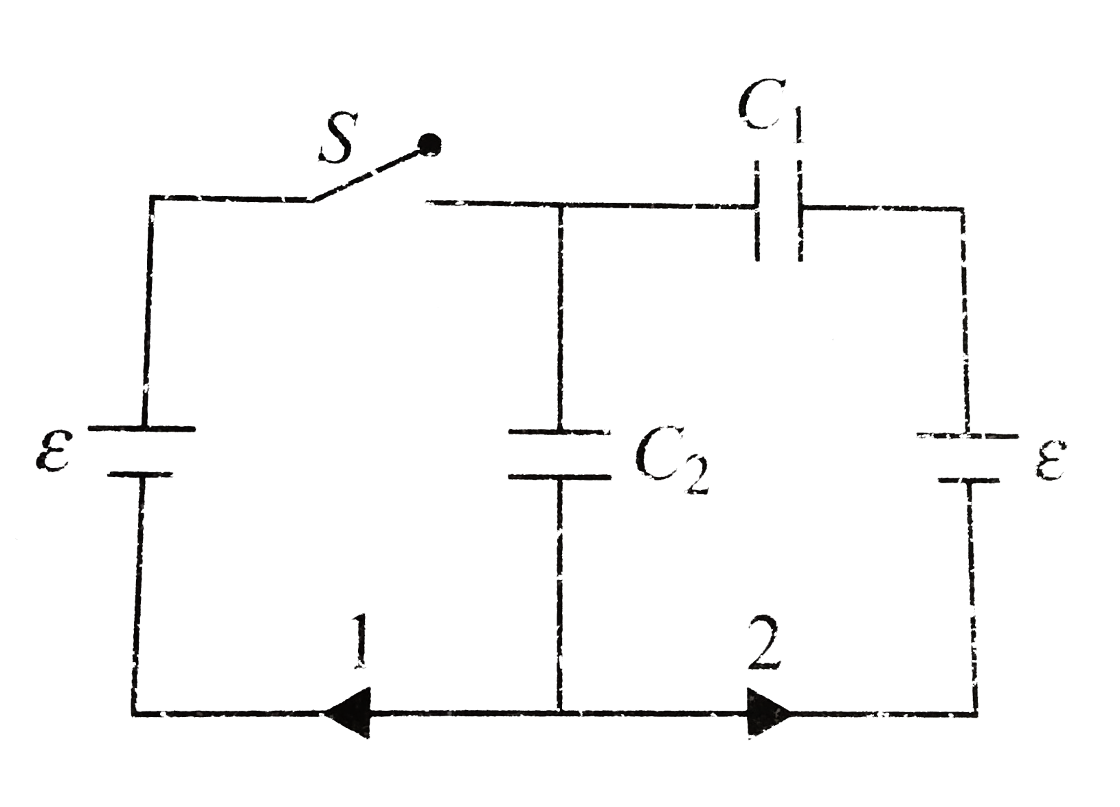
The charge that will flow in direction 2 is
View Solution
