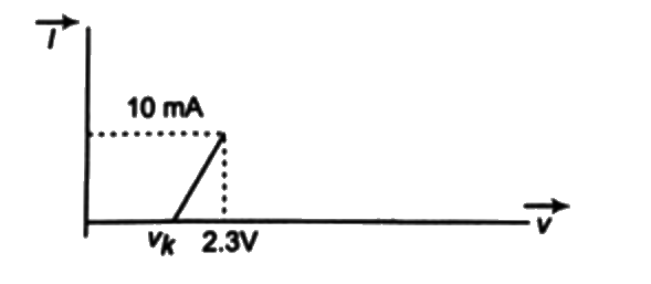
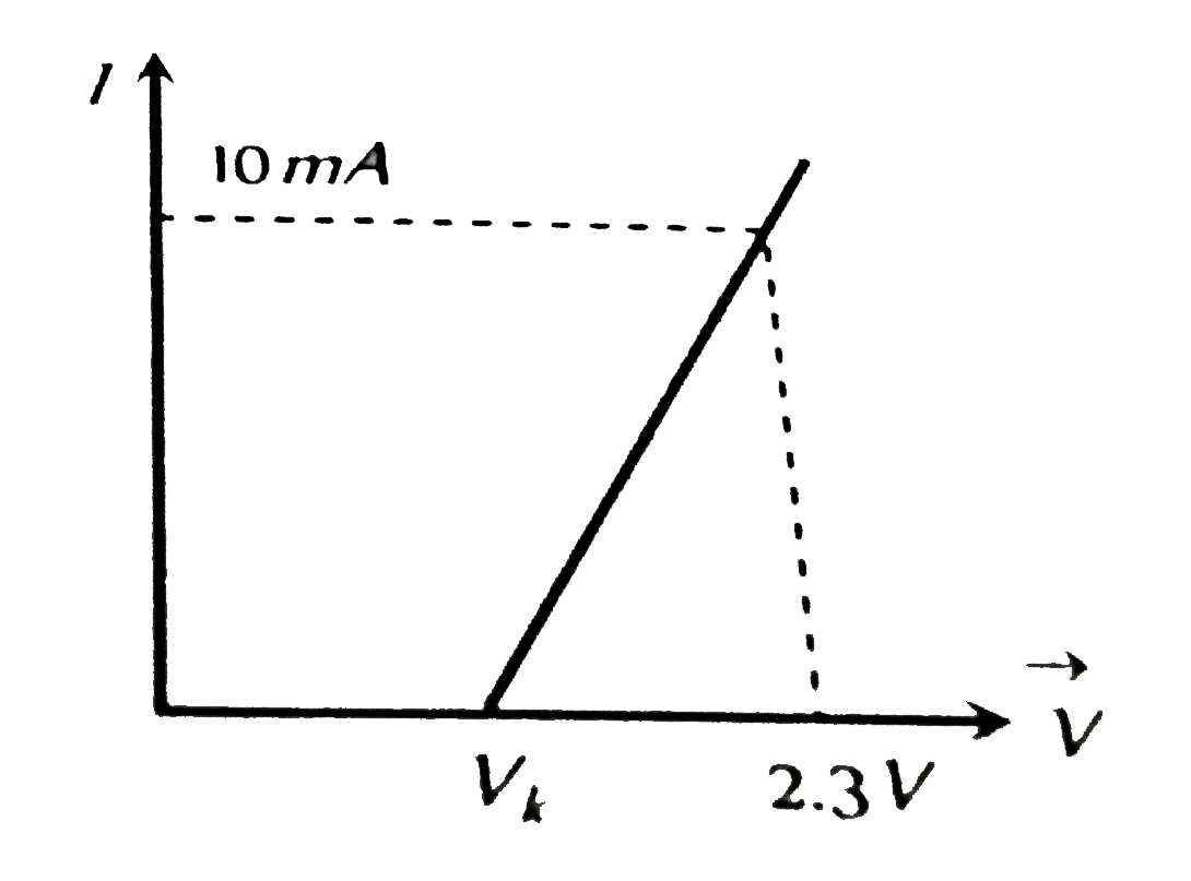
The resistance of a germanium junction diode whose V−I is shown in figure is (Vk=0.3V)
5kΩ
0.2kΩ
2.3kΩ
(102.3)kΩ
The correct Answer is:B
Topper's Solved these Questions
- ELECTRONICSBOOK - ERRORLESS CHAPTER - ELECTRONICSEXERCISE - Selv Evaluation Test
23 Videos
- ELECTRONICSBOOK - ERRORLESS CHAPTER - ELECTRONICSEXERCISE - Objective Questions
12 Videos
- ELECTRON, PHOTON, PHOTOELECTRIC EFFECT AND X-RAYSBOOK - ERRORLESS CHAPTER - ELECTRON, PHOTON, PHOTOELECTRIC EFFECT AND X-RAYSEXERCISE - Self Evaluation Test
3 Videos
- ELECTROSTATICS BOOK - ERRORLESS CHAPTER - ELECTROSTATICS EXERCISE - Ordinary Thinking Objective Questions (Electric Flux and Gauss.s Law)
28 Videos
Similar Questions
Knowledge Check
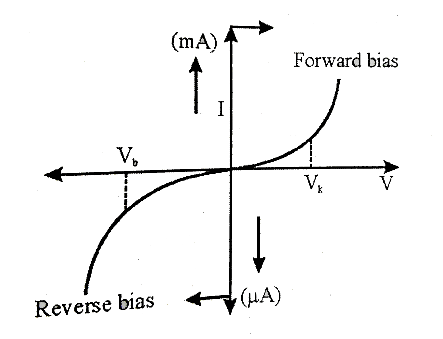
The V-I characterisctic for a p-n junction diode is plotted as shown in the figure. From the plot we can conclude that
[Vb→ breakdown voltage, Vk→ knee voltage]Athe forward bias resistance of diode is very high, almost infinity for small values of V and after a certain value it becomes very lowBthe reverse bias resistance of diode is very high in the beginning upto breakdown voltage is not achievedCboth forward and reverse bias resistances are same for all voltagesDboth (A) and (B) are correctThe V-I characteristic of a silicon diode is shown in figure . The resistance of the diode at ID=15 mA is
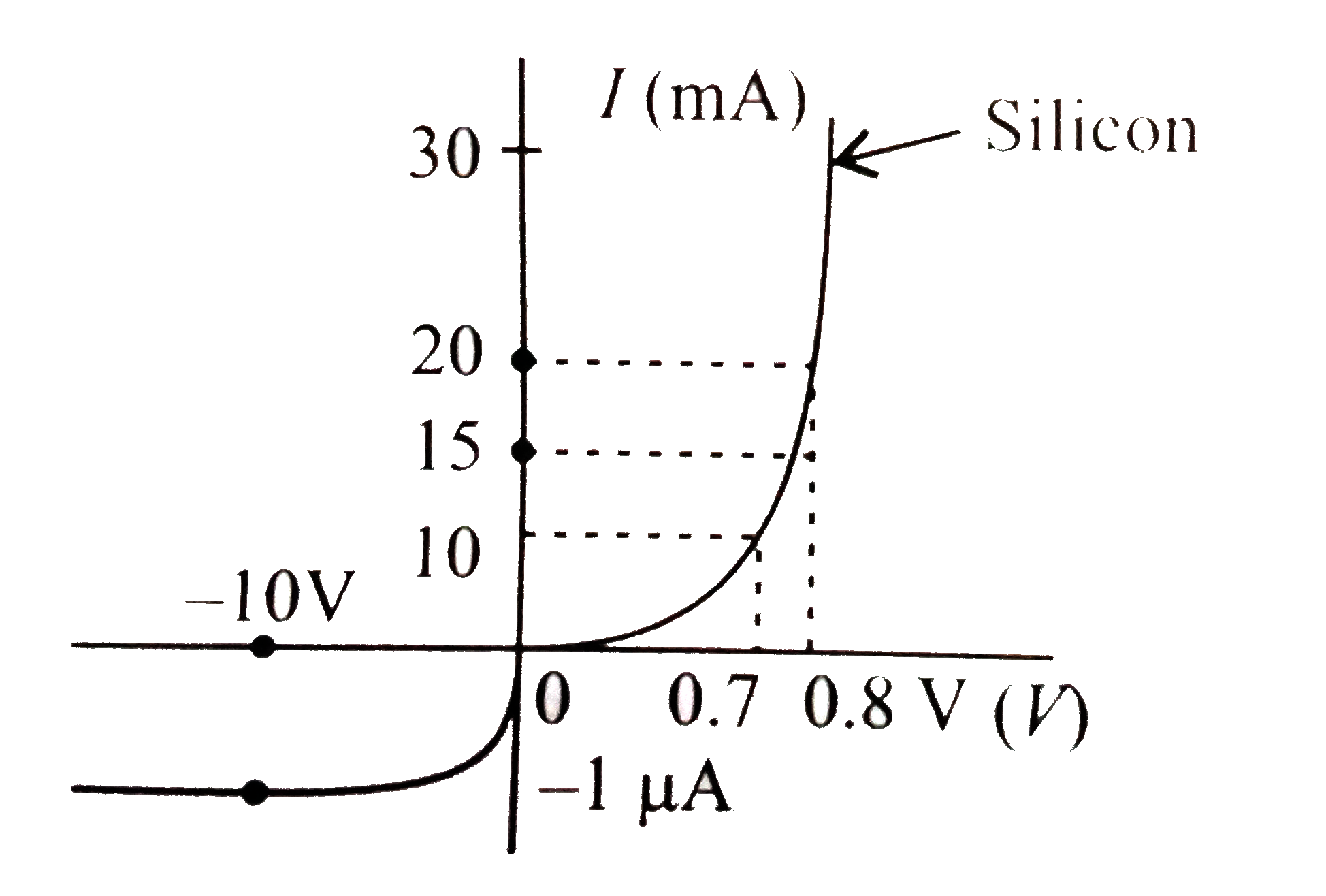 A5ΩB10ΩC2ΩD20Ω
The V-I characteristic of a silicon diode is shown in figure . The resistance of the diode at ID=15 mA is
 A5ΩB10ΩC2ΩD20Ω
Name the junction diode whose I-V characteristics are shown adjoining

View SolutionThe forward characteristic curve of a junction diode is shown in figure below:
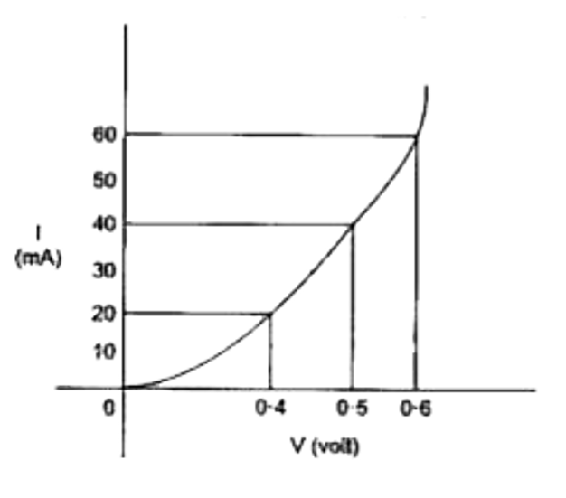
Calculate the resistance of the diode at:
y= 0.5V
View SolutionThe forward characteristic curve of a junction diode is shown in figure below:
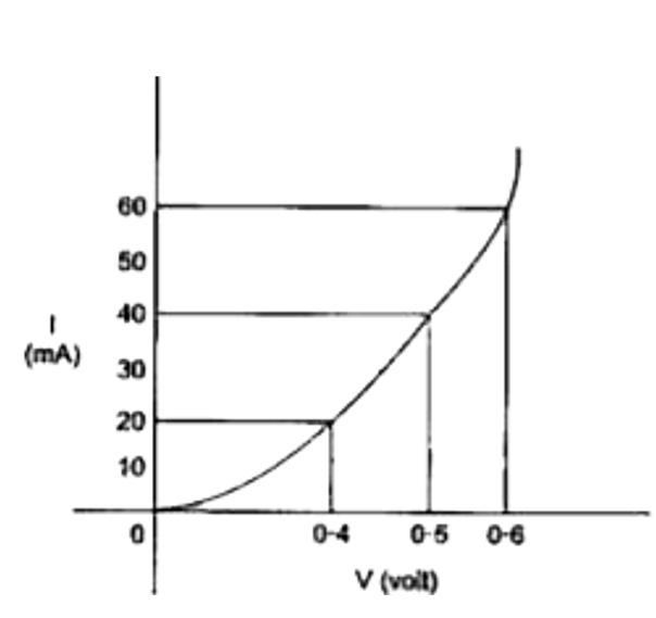
Calculate the resistance of the diode at:
I= 60mA
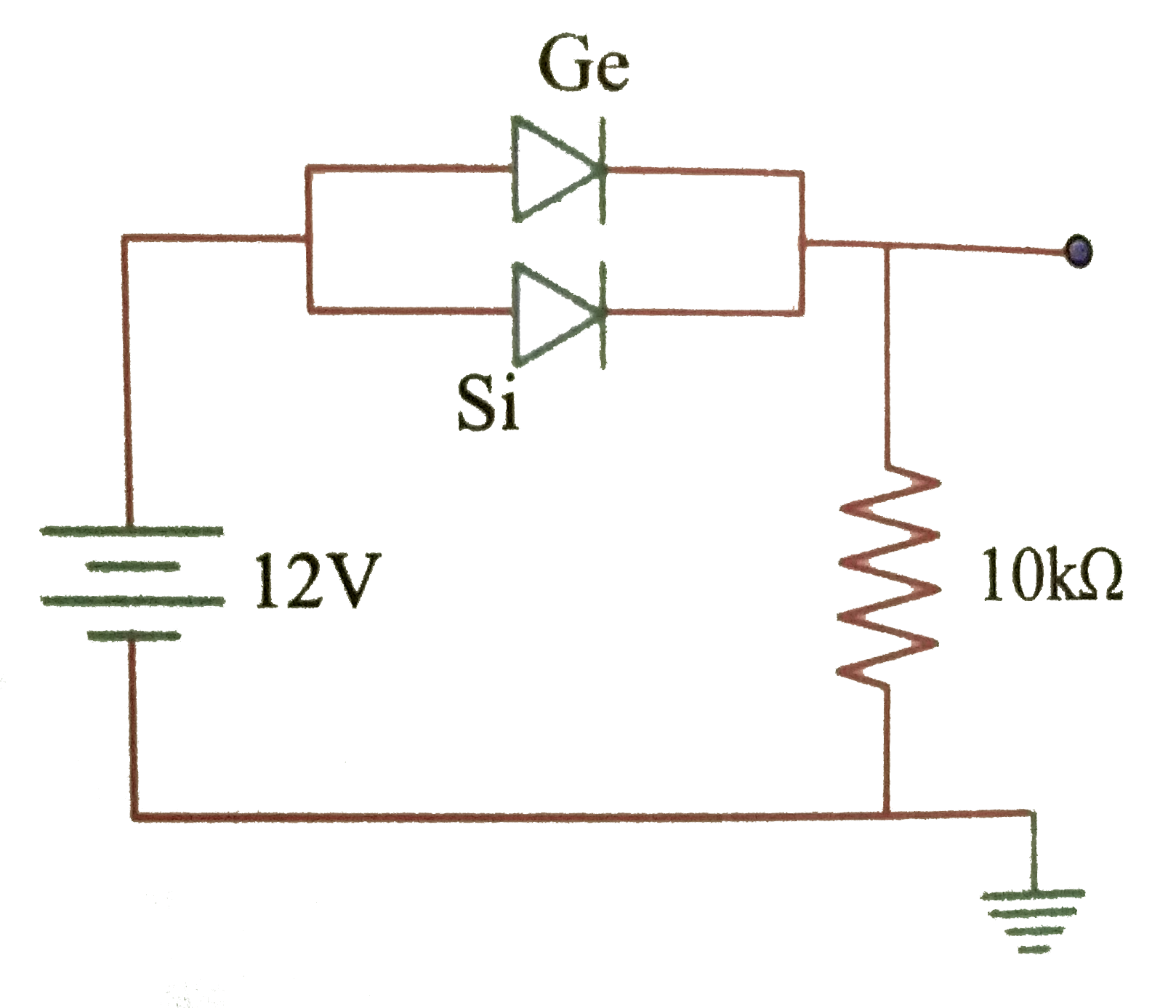
View SolutionTwo junction diodes, one of germanium (Ge) and other of silicon (Si) are connected as shown in fig to a battery of 12V and a load resistance 10kΩ. The germanium diode conducts at 0.3V and silicon diode at 0.7V. When current flows in the circuit, the potential of terminal Y will be
 .
.
View SolutionTwo junction diodes, one of germanium (Ge) and other of silicon (Si) are connected as shown in fig to a battery of 12V and a load resistance 10kΩ. The germanium diode conducts at 0.3V and silicon diode at 0.7V. When current flows in the circuit, the potential of terminal Y will be
 .
.
View Solution

