A potential divider is used to give outpurs of 4V and 8V from a 12V source. Which combination of resistance, (R1,R2,R3 gives the correct voltages? (R_(1) : R_(2) : R_(3)
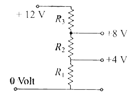
2:1:2
1:1:1
2:2:1
1:1:2
The correct Answer is:B
Step by step video, text & image solution for A potential divider is used to give outpurs of 4V and 8V from a 12V source. Which combination of resistance, (R_(1), R_(2), R_(3) gives the correct voltages? (R_(1) : R_(2) : R_(3) by Physics experts to help you in doubts & scoring excellent marks in Class 12 exams.
Topper's Solved these Questions
- BOOK - CENGAGE PHYSICSCHAPTER - ELECTRIC CURRENT & CIRCUITSEXERCISE - Kirchhoff s Law and Grouping Cells15videos
ELECTRIC CURRENT & CIRCUITS
- BOOK - CENGAGE PHYSICSCHAPTER - ELECTRIC CURRENT & CIRCUITSEXERCISE - Kirchhoff s law and simple circuits15videos
ELECTRIC CURRENT & CIRCUITS
- BOOK - CENGAGE PHYSICSCHAPTER - ELECTRIC CURRENT & CIRCUITSEXERCISE - Combination of Resistance 114videos
ELECTRIC CURRENT & CIRCUITS
- BOOK - CENGAGE PHYSICSCHAPTER - ELECTRIC CHARGES AND FIELDSEXERCISE - QUESTION BANK40videos
ELECTRIC CHARGES AND FIELDS
- BOOK - CENGAGE PHYSICSCHAPTER - ELECTRIC CURRENT AND CIRCUITEXERCISE - Interger8videos
ELECTRIC CURRENT AND CIRCUIT
Similar Questions
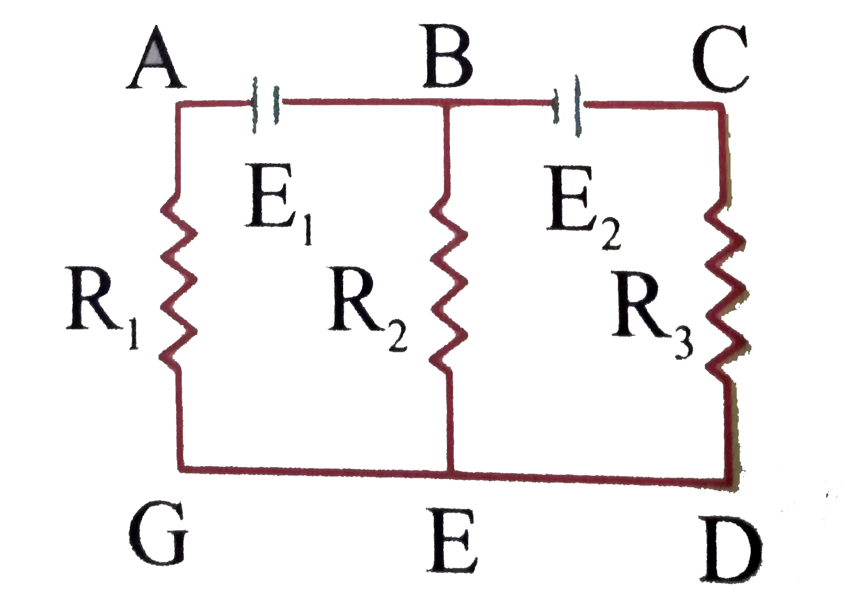
In the given circuit values are as follows
ε=2V,ε2=4V,R1=1Ω and R2=R3=1Ω.
Calculate the current through R1,R2 and R3View SolutionFind the currents in the Y connection of 3 resistances R1=10Ω, R2=20Ω and R3=30Ω. When the terminals of R1 , R3 and R3 are maintained at potentials V1 = 10V, V2=6V and V3 = 15V.
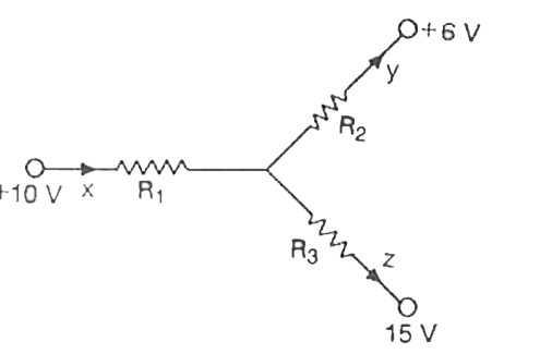 View Solution
Knowledge Check
- Question 1 - Select One
A potential divider is used to give outputs of 4 V and 8 V from a 12 V source. Which combination of resistances, ( R , R, R ) gives the correct voltages ? R : R : R
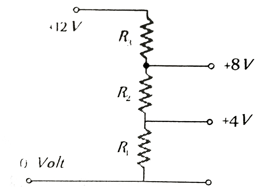 A2:1:2B1:1:1C2:2:1D1:1:2
 - Question 2 - Select One
A potential divider is used to given outputs of 2V and 3V form a 5V source, as shown in fig.
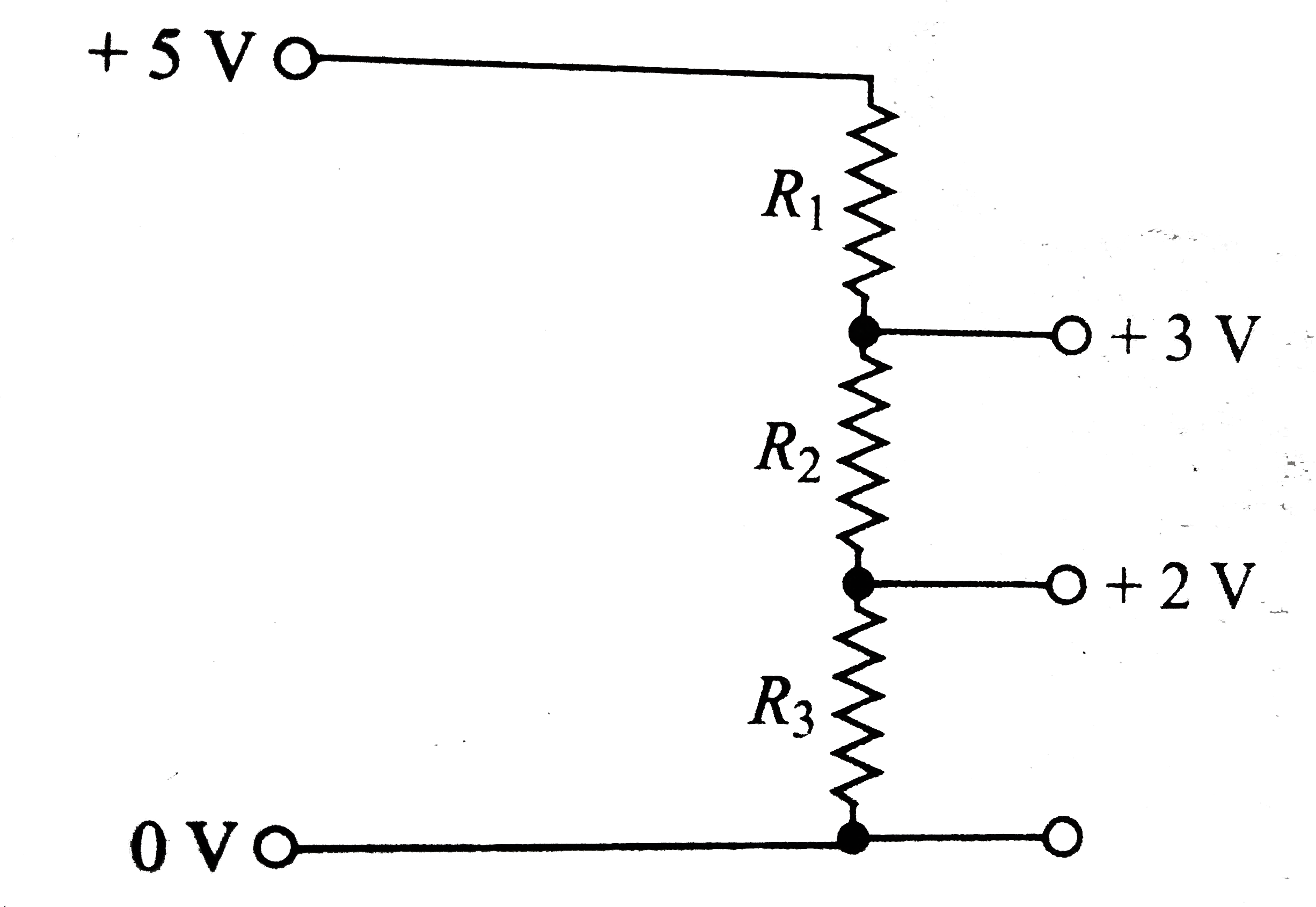
Which combination of resistance R1,R2,andR3 gives the correct voltages?A2B2C2D3 - Question 3 - Select One
The circuit is shown in the following figure. The potential at points A, B, C, D and O are given. The currents in the resistance R1,R2 and R3 are in the ratio of 4:2:1. What is the ratio of resistance R1,R2,R3 and R4 ?
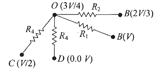 A3:2:12:16B2:3:36:12C4:3:12:32D3:4:14:32
(a) State the principle of working of a galvanometer.
(b) Agalvanometer of resistance G is converted into a voltmeter to measure up to V volts by connecting a resistance R1 , in series with the coil. If a resistance R2 is connected in series with it, then it can measure up to V/2 volts. Find the resistance, in terms of R1andR2, required to be connected to convert it into a voltmeter that can read up to 2 V. Also find the resistance G of the galvanometer in terms of R1 and R2.View SolutionTwo ideal batteries of emfV1andV2 and three resistance R1R2andR3 are connected The current in resistance R2 would be zero if
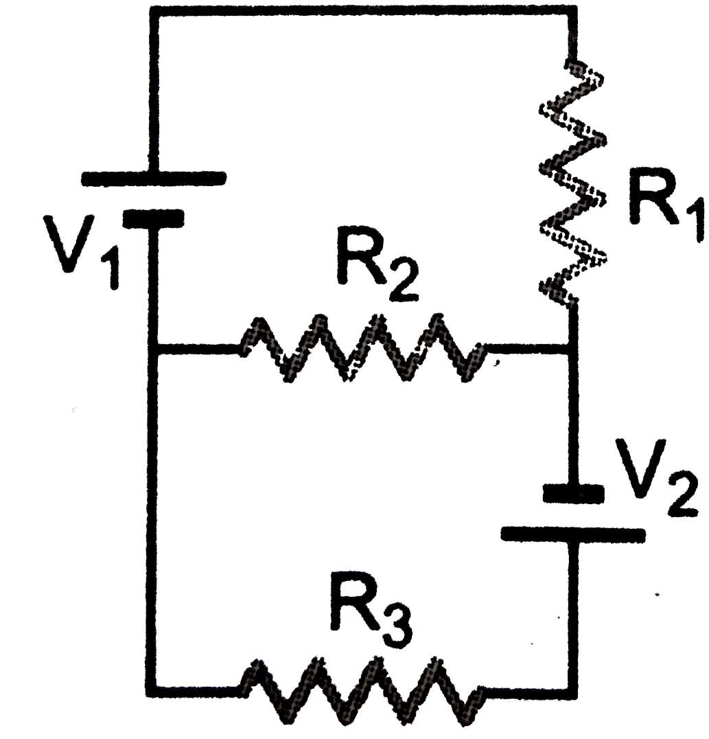 View Solution
The possible percentage error in computing the parallel resistance R of three resistances R1,R2,R3 from the formula 1R=1R1+1R2+1R3, if R1,R2,R3 are each 1.2% in error, is
View SolutionA resistance R1 is connected to a source of constant voltage . On connecting a resistance R2 in series with R1
View SolutionAn N-P-N transistor in a common emitter mode is used as a simple voltage amplifier with a collecter current of 4mA. The terminal of a 8 V battery is connected to the collector through a load ressitance RL and to the base through a resistance RB. The collector-emitter voltage VCE=4V base -emitter voltage
VBE=0.6V and base current amplification factor βd.c.=100.Find the values of RL and RB.View Solution

