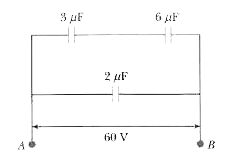
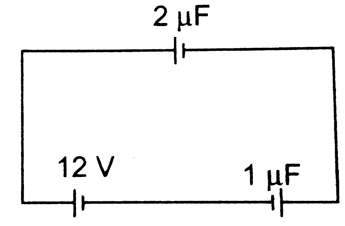
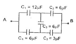
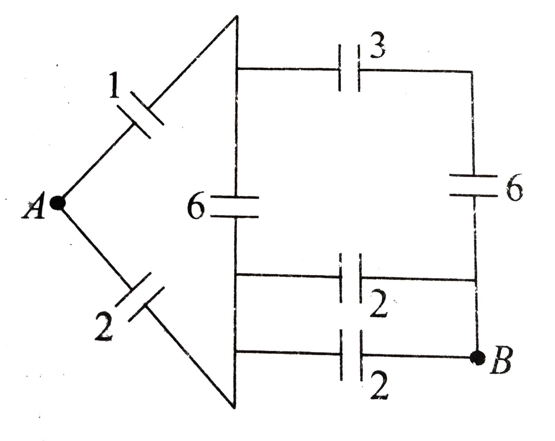
In the circuit shown, the potential difference across the 3μF capacitor is V and the equivalent capacitance between A and B is C Then:
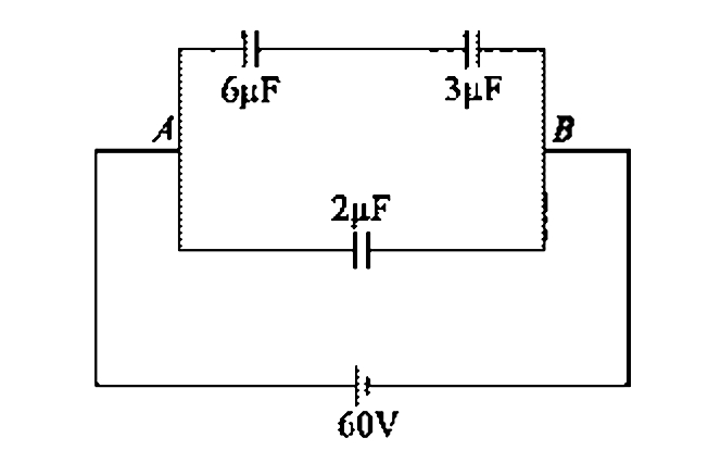
C=4μF
C=11μF
V=20V
V=40V
The correct Answer is:A, D
Step by step video, text & image solution for In the circuit shown, the potential difference across the 3muF capacitor is V and the equivalent capacitance between A and B is C Then: by Physics experts to help you in doubts & scoring excellent marks in Class 12 exams.
Updated on:21/07/2023Topper's Solved these Questions
- CAPACITANCEBOOK - PHYSICS GALAXY - ASHISH ARORACHAPTER - CAPACITANCEEXERCISE - UNSOLVED NUMERICAL PROBLEMS
40 Videos
- CAPACITANCEBOOK - PHYSICS GALAXY - ASHISH ARORACHAPTER - CAPACITANCEEXERCISE - NUMERICAL MCQS
56 Videos
- ATOMIC PHYSICSBOOK - PHYSICS GALAXY - ASHISH ARORACHAPTER - ATOMIC PHYSICSEXERCISE - Unsolved Numerical Problems
39 Videos
- CURRENT ELECTRICITYBOOK - PHYSICS GALAXY - ASHISH ARORACHAPTER - CURRENT ELECTRICITYEXERCISE - All Questions
389 Videos
Similar Questions
Knowledge Check
In the circuit shown in the figure, the potential difference across the 4.5μF capacitor is
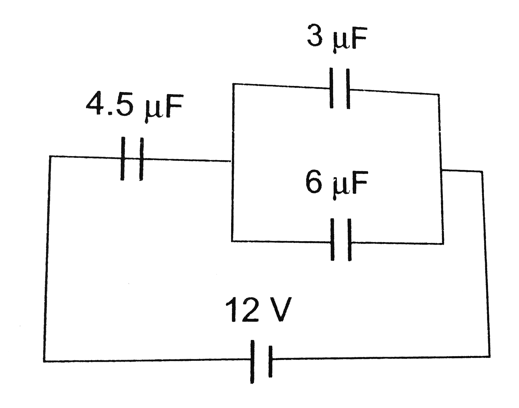 A83voltsB4 voltsC6 voltsD8 volts
The equivalent capacitance between A and B in the circuit shown is
 A6 muFB1.5 muFCzeroD2 muF
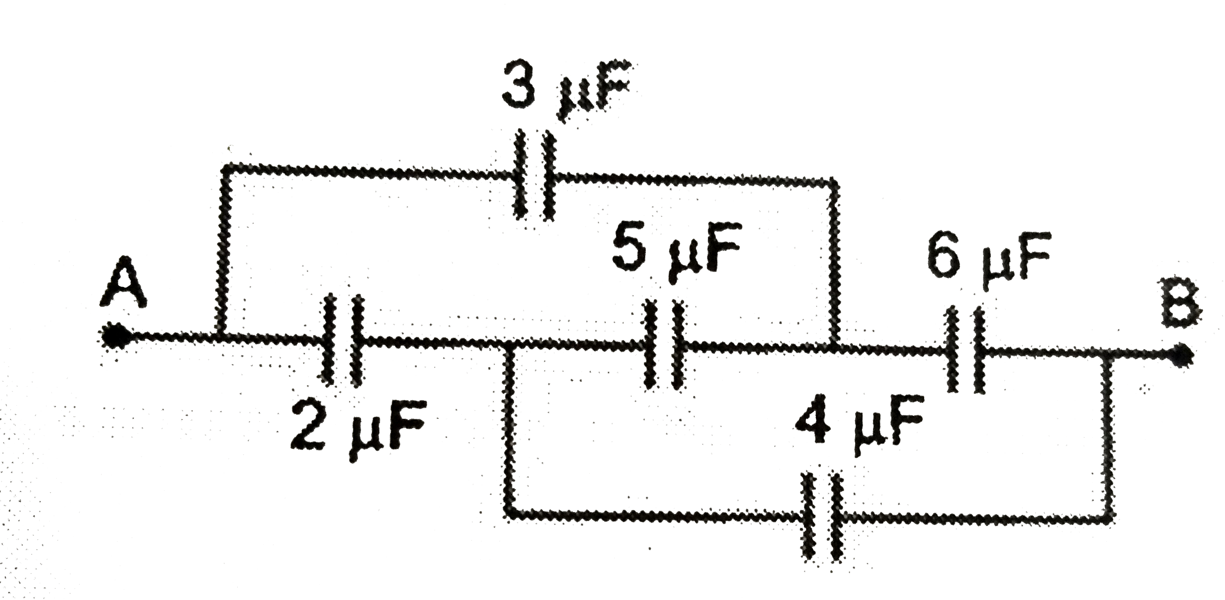
In the circuit shown, the equivalent capacitance between the points A and B isA103μFB154μFC125μFD256μF
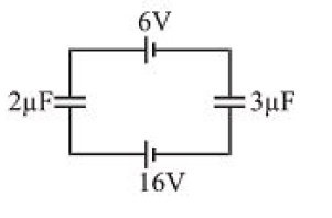
What is the potential difference across 2μF capacitor in the circuit shown?
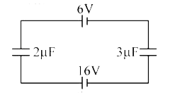
View SolutionWhat is the potential difference across 2μF capacitor in the circuit shown?
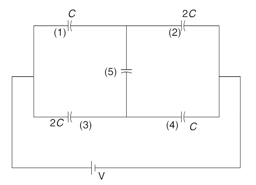
View SolutionIn the circuit shown in the Figure, find the ratio of potential difference across capacitor 1 and 2. The capacitance values are as indicated in the Figure.
View Solution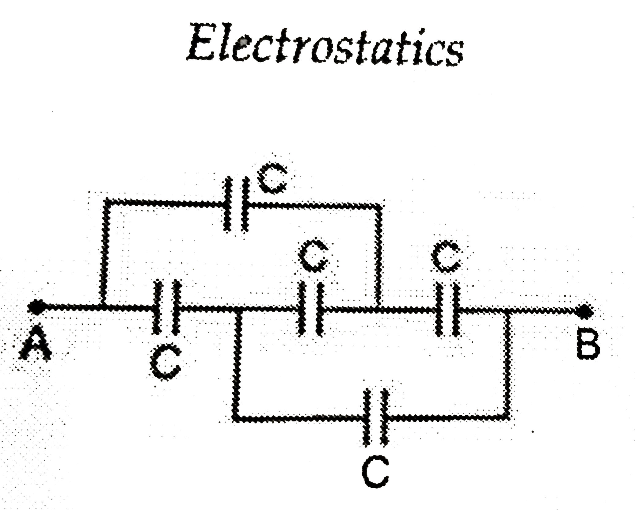
In the circuit shown, the equivalent capacitance between the points A and B is
View SolutionAll the capacitances shown in figure are in μF. Find the equivalent capacitance between A and B.
View Solution

