To measure a small emf (of, say, a galvanic cell or a thermocouple) the so-called balancing method is employed. The circuit diagram of this method is shown in the figure. Here ~x is the sought emf, is the source of current whose emf is much higher than ~x, G is a galvanornetcr with the zero in the middle of the scale, A is an ammeter, and R is the resistance box. How should one operate this circuit so as to ensure an accuracy in measuring ~x that is determined by the precision of the measuring devices?
Step by step video & image solution for To measure a small emf (of, say, a galvanic cell or a thermocouple) the so-called balancing method is employed. The circuit diagram of this method is shown in the figure. Here ~x is the sought emf, is the source of current whose emf is much higher than ~x, G is a galvanornetcr with the zero in the middle of the scale, A is an ammeter, and R is the resistance box. How should one operate this circuit so as to ensure an accuracy in measuring ~x that is determined by the precision of the measuring devices? by Physics experts to help you in doubts & scoring excellent marks in Class 12 exams.
Topper's Solved these Questions
Similar Questions
Knowledge Check
- Question 1 - Select One
The EMF of a galvanic cell is measured by
AammeterBgalvanometerCvoltmeterDpotentiometer - Question 2 - Select One
The standard emf of a galvanic cell can be calculated from
Athe size of the electrodeBthe pH of the solutionCthe amount of metal in the anodeDthe E∘ values of the half cells - Question 3 - Select One or More
If the e.m.f of a galvanic cell is neagative, it implies that:
Athe cell reaction is spontaneousBthe cell reaction is non-spontaneousCthe cell reaction is exothermicDthe cell is working in reverse direction
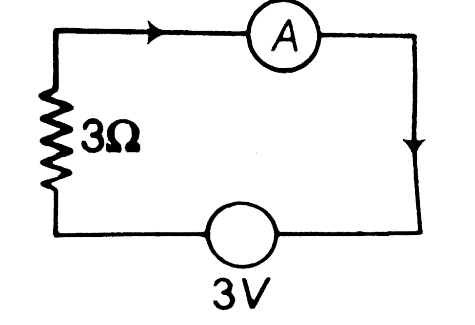
In the given circuit the current is to be measured the value of the current if the ammeter shown is a galvanometer with a resistance Rg=60ω is
 View Solution
In the circuit, the current is to be measured. What is the value of the current if the ammeter shown :
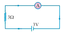
(a) is a galvanometer with a resistance RG=60Ω,View SolutionThe emfs and resistance in the circuit (as shown in the figure) have the following values.
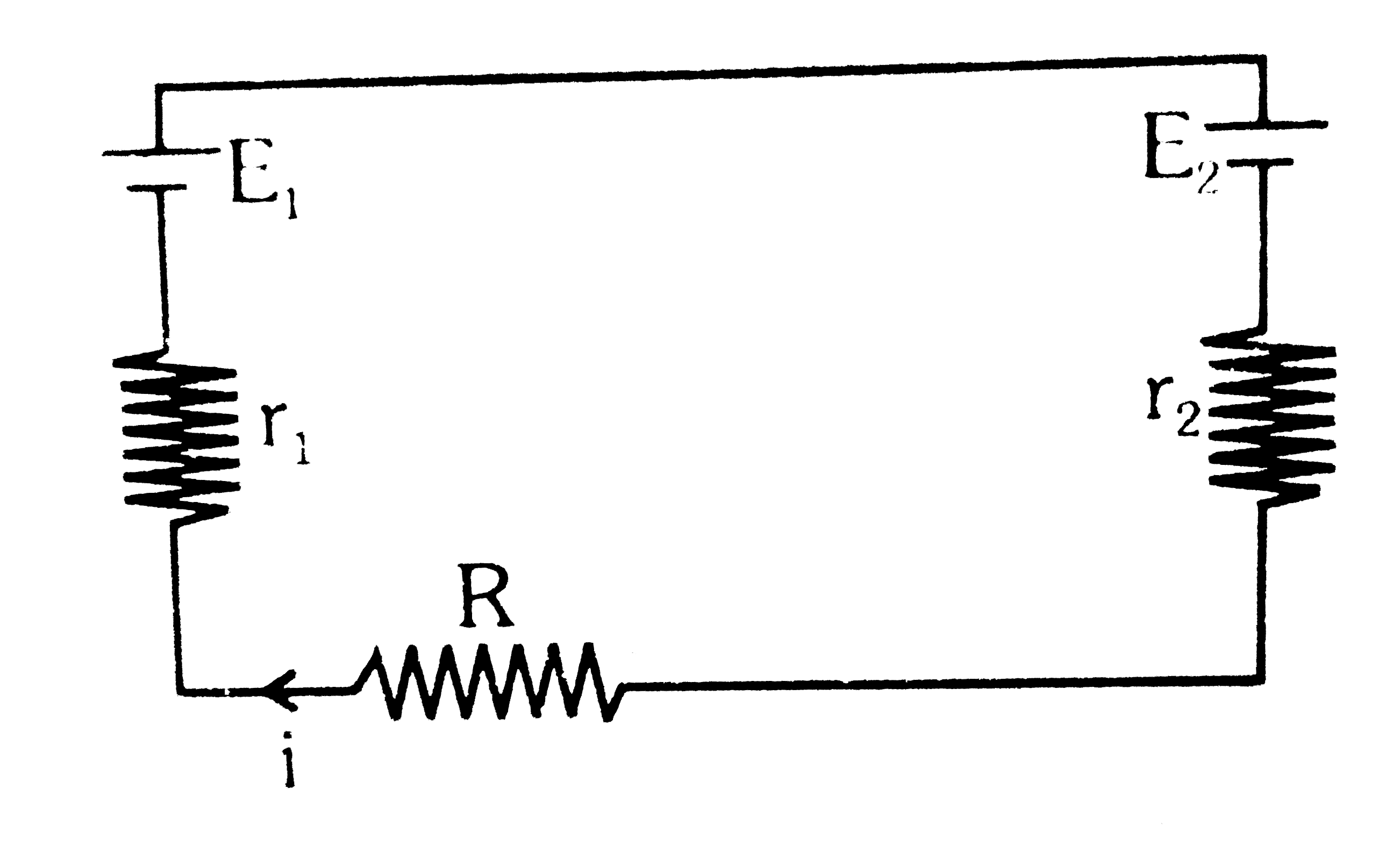 View Solution
The equivalent resistance across the terminals of source of e.m.f. 24V for the circuit shown in the figure is
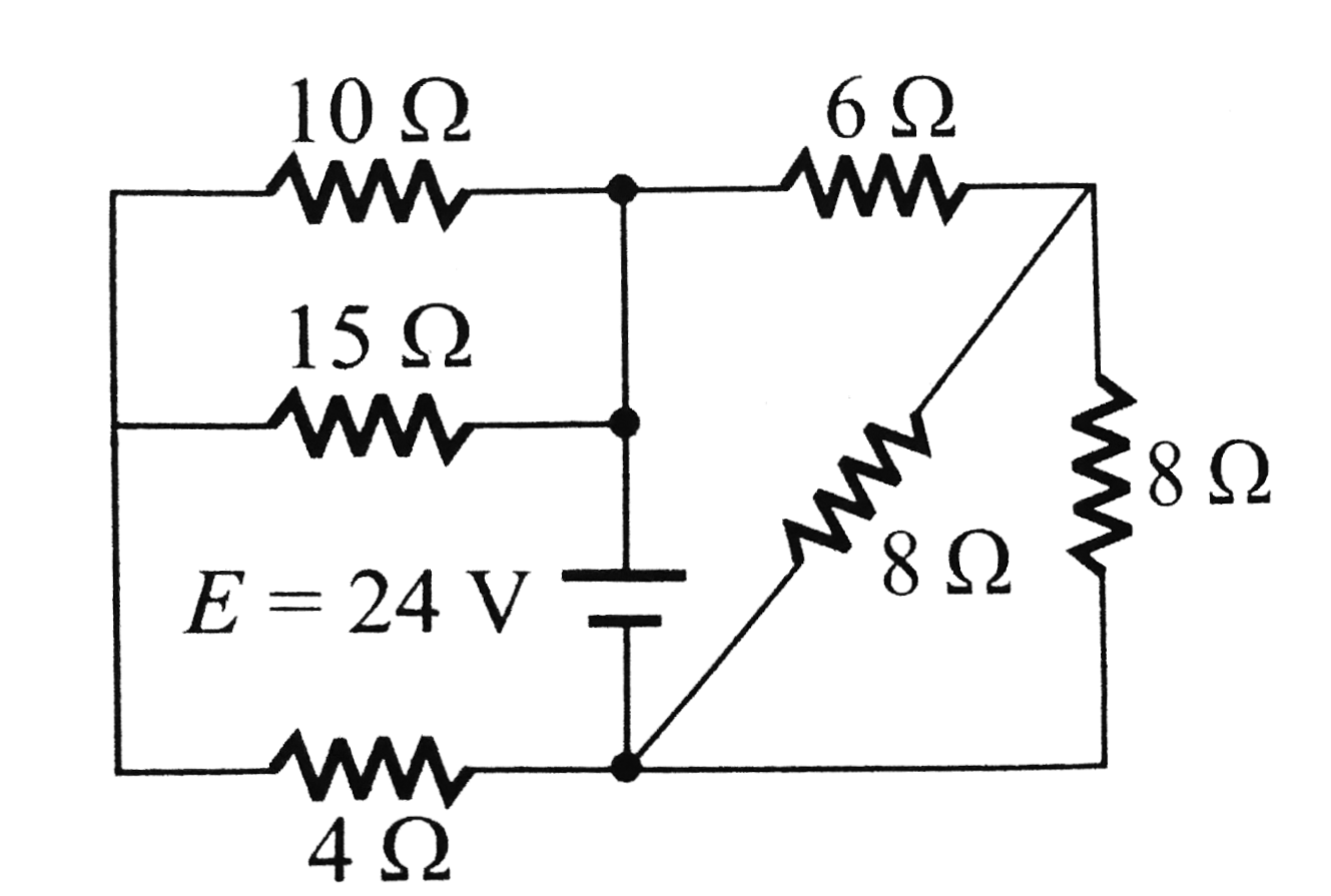 View Solution
For the circuit (figure) the currents is to be measured. The ammeter shown is a galvanometer with a resistance RG=60.00Ω converted to an ammeter by a shunt resistance rS=0.02Ω. The value of the current is
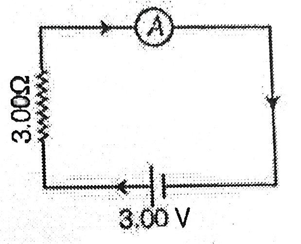 View Solution


