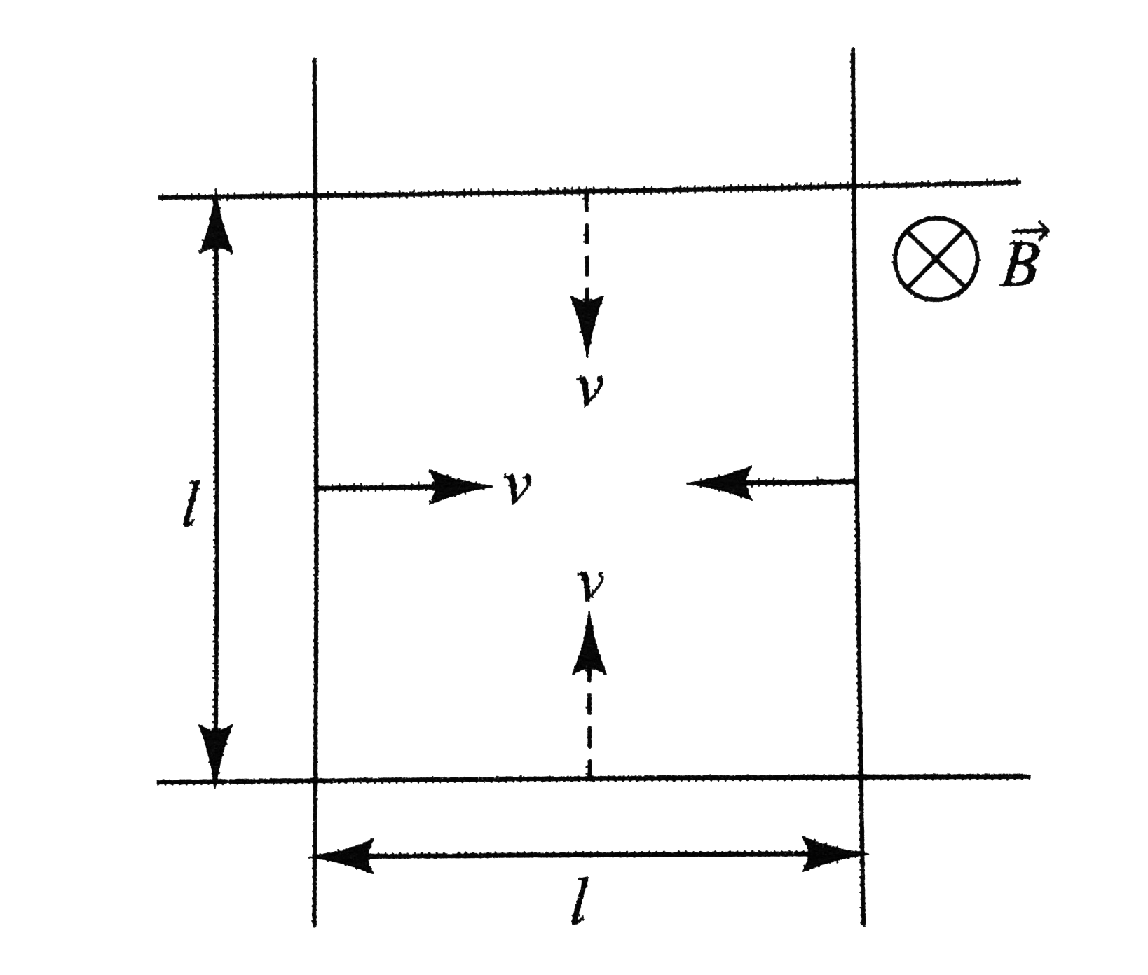
In the figure shown the four rods have λ resistance per unit length. The arrangement is kept in a magnetic filed of constant magnitude B and directed perpendicular to the plane of the figure and direction inwards. Intially the sides as shown from a square. Now each wire starts moving with constant velocity v towards opposite wire. Find as a function of time:
(a) induced emf in the circuit
(b) induced current in the circuit with direction

The correct Answer is:a
Step by step video, text & image solution for In the figure shown the four rods have lambda resistance per unit length. The arrangement is kept in a magnetic filed of constant magnitude B and directed perpendicular to the plane of the figure and direction inwards. Intially the sides as shown from a square. Now each wire starts moving with constant velocity v towards opposite wire. Find as a function of time: (a) induced emf in the circuit (b) induced current in the circuit with direction by Physics experts to help you in doubts & scoring excellent marks in Class 12 exams.
Topper's Solved these Questions
- BOOK - CENGAGE PHYSICSCHAPTER - ELECTROMAGNETIC INDUCTIONEXERCISE - single correct8videos
ELECTROMAGNETIC INDUCTION
- BOOK - CENGAGE PHYSICSCHAPTER - ELECTROMAGNETIC INDUCTIONEXERCISE - comprehensive type7videos
ELECTROMAGNETIC INDUCTION
- BOOK - CENGAGE PHYSICSCHAPTER - ELECTROMAGNETIC INDUCTIONEXERCISE - single correct10videos
ELECTROMAGNETIC INDUCTION
- BOOK - CENGAGE PHYSICSCHAPTER - ELECTROMAGENTIC INDUCTIONEXERCISE - QUESTION BANK40videos
ELECTROMAGENTIC INDUCTION
- BOOK - CENGAGE PHYSICSCHAPTER - ELECTRON,PHONTS,PHOTOELECTRIC EFFECT & X-RAYSEXERCISE - dpp 3.315videos
ELECTRON,PHONTS,PHOTOELECTRIC EFFECT & X-RAYS
Similar Questions
in fig. The four rods have λ resistance per unit length. The arrengement is kept in a magnetic field of constant magnitude B and directed perpendicular to the plane of the figure and directing in ward. Initially, the sides as shown form a square. Now each wire starts moving with constant velocity v toward the opposite wire.
Find as a function of time:
(a) induced emf in the circuit.
(b) induced current in the circuit with direction.
( c ) force required on each wire to keep its velocity consatnt.
(d) total power required to maintain constant velocity.
(e) thermal power developed in the circuit.
 View Solution
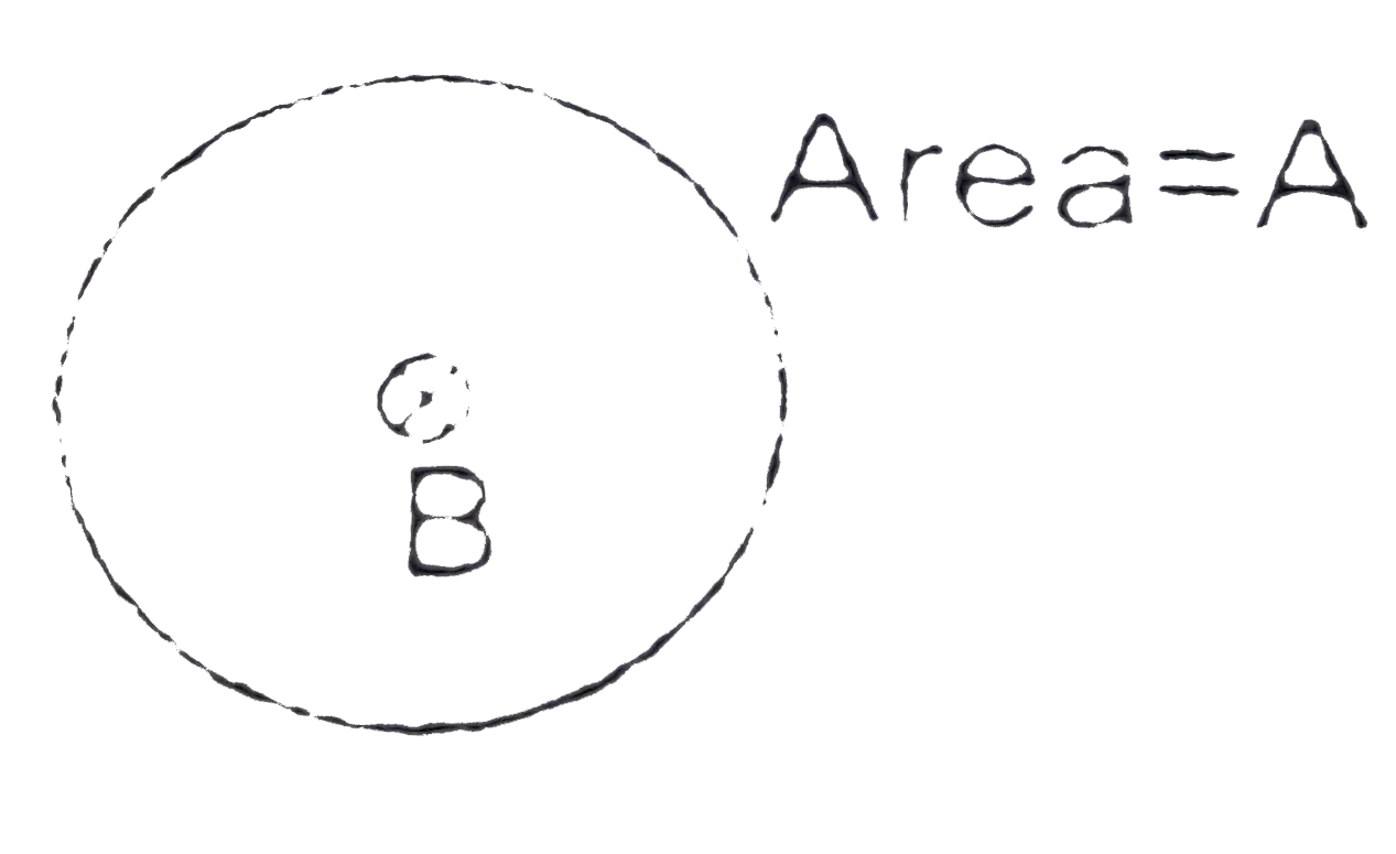
Find the emf induced in the coil shown in figure.The magnetic field is perpendicular to the plane of the coil and is constant.
 View Solution
Knowledge Check
- Question 1 - Select One
In the figure shown the four rods have λ resistance per unit length . The arrangement is kept in a magnetic field of constant magnitude B and directed perpendicular to the plane of the figure and direction inwards . Initially the sides as shown form a square . Now each wire starts moving with constant velocity v towards opposite wire . Find as a function of time .

Induced current in the circuit with directionA2BvλBBvλCBv2λDzero - Question 2 - Select One
In the figure shown the four rods have λ resistance per unit length . The arrangement is kept in a magnetic field of constant magnitude B and directed perpendicular to the plane of the figure and direction inwards . Initially the sides as shown form a square . Now each wire starts moving with constant velocity v towards opposite wire . Find as a function of time .

Thermal power developed in the circuit.A4B2v2λ(l−2vt)B4B2v2λ(l−vt)C4B2v2λ(l+2vt)DB2v2λ(l−2vt) - Question 3 - Select One
In the figure shown the four rods have λ resistance per unit length . The arrangement is kept in a magnetic field of constant magnitude B and directed perpendicular to the plane of the figure and direction inwards . Initially the sides as shown form a square . Now each wire starts moving with constant velocity v towards opposite wire . Find as a function of time .

Force required on each wire to keep its velocity constant .AB2vλ(l+2vt)BB2vλ(l−vt)CzeroDB2vλ(l−2vt)
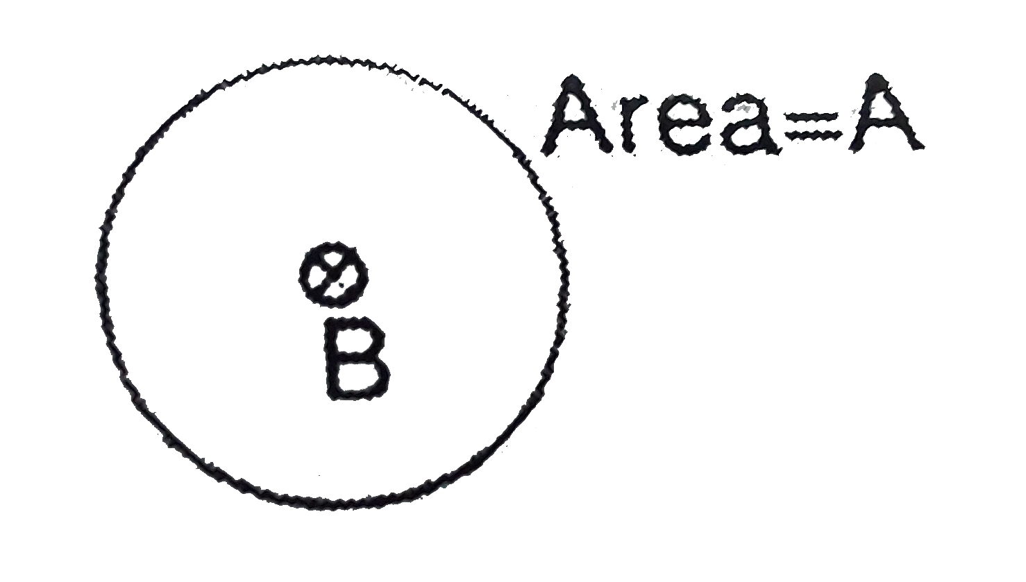
Find the emf induced in the coil shown in figure. The magnetic field is perpendicular to the plane of the coil and is constant.
 View Solution
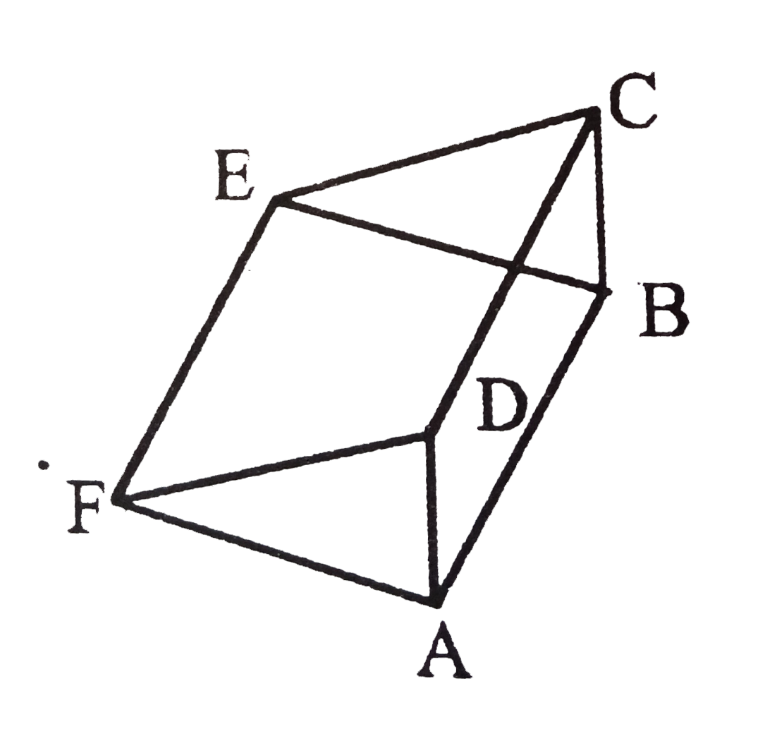
In the circuit shown in figure, all wires have equal resistance r. Find the equivalent resistance between A and B
 View Solution
In the figure shown the four rods have λ resistance per unit length . The arrangement is kept in a magnetic field of constant magnitude B and directed perpendicular to the plane of the figure and direction inwards . Initially the sides as shown form a square . Now each wire starts moving with constant velocity v towards opposite wire . Find as a function of time .

Total power required to maintain constant velocity .View SolutionFigure shows a wire sliding on two parallel, conducting rails placed at a separation L . A magnetic field B exists in a direction perpendicular to the plane of the rails. What force is necessary to keep the wire moving at a constant velocity V ?
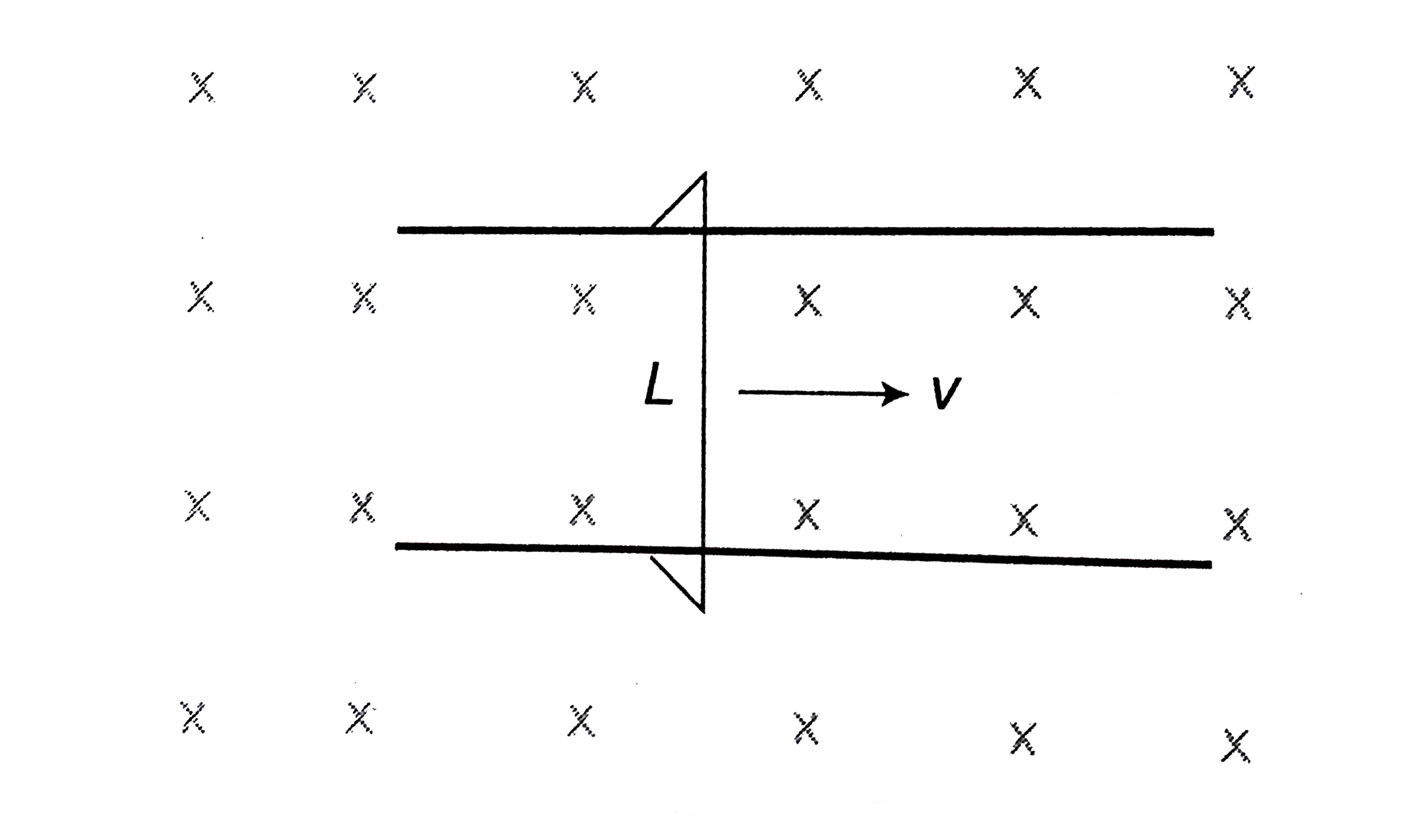 View Solution
A wire KMN moves along the bisector of the angle θ with a constant velocity v in a uniform magnetic field B perpendicular to the plane of the paper and directed inward. Which of the following is correct?
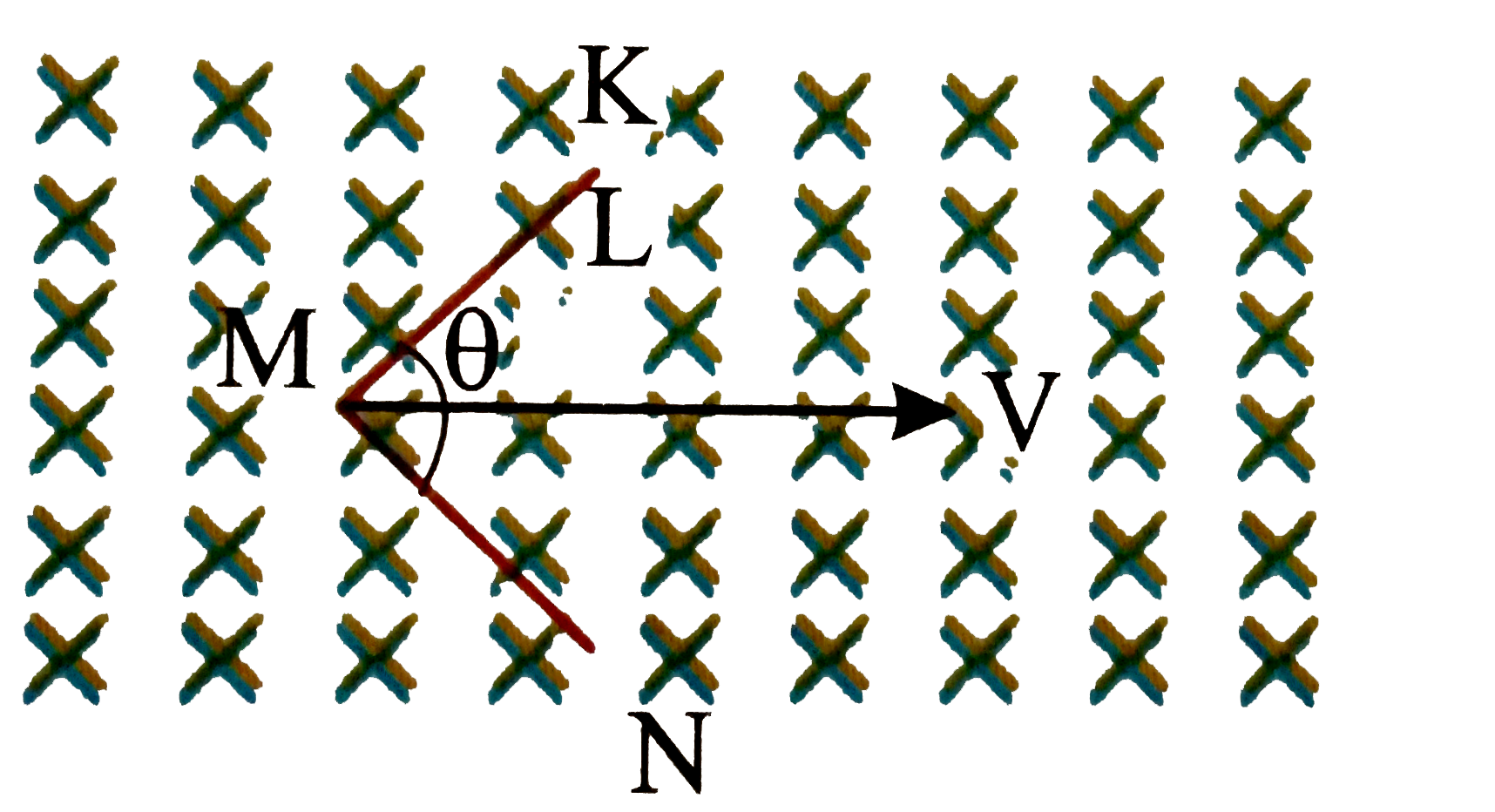 View Solution

