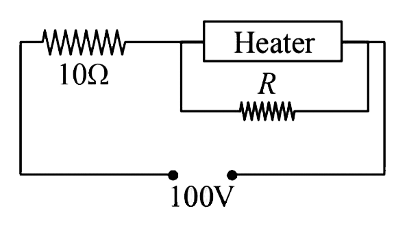
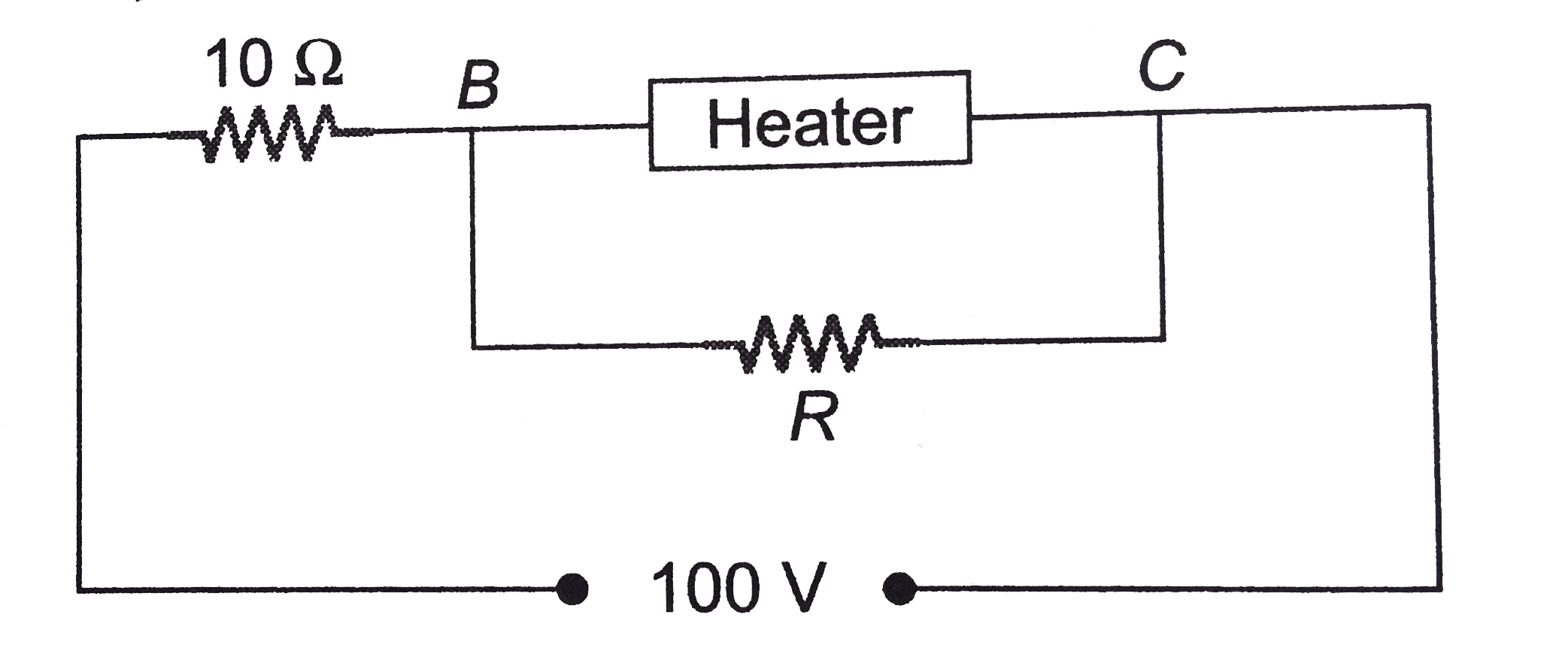
A heater is designed to operate with a power of 1000 walts in a 100 volt line. It is connected in a combinations with a resistance of 10 ohms and a resistance R to a 100 volts mains as shown in figure. What should be the value of R so that the heater operates with a power of 62.5 watts.
 .
.
Step by step video & image solution for A heater is designed to operate with a power of 1000 walts in a 100 volt line. It is connected in a combinations with a resistance of 10 ohms and a resistance R to a 100 volts mains as shown in figure. What should be the value of R so that the heater operates with a power of 62.5 watts. . by Physics experts to help you in doubts & scoring excellent marks in Class 12 exams.
Updated on:21/07/2023Topper's Solved these Questions
Similar Questions
A heater is designed to operate with a power of 1000W in a 100V line. It is connected in combination with a resistace of 10Ω and a resitance. R, to a 100V mains, as shown in Fig. 6.6 What should be the value of R so that the heat operates with a power of 62.5 W ?
View SolutionIf two buibs of 25 W and 100 W rated at 400 V are connected in series across a440 V supply, will both the bulb fuse? If not, then which one ?
(b) Two bulbs rated at 60 W and 100 W (220 V) are connected (i) in series and (ii) in parallel. Find the heat dissipated in the bulbs and also the total heat dissipatedin the circuit.
(c) A heater is designed to operate with a power of1000 watts in a 100 volt line. It is connected with an identical heater (B) in series and a100 V second heater (C) in parallel as shown. What should be the resistance of C so that the heater A may operate at a power level of 62.5 watts, if the entire combination is connected across a 100 V line

View Solution
Knowledge Check
A heater is designed to operate with a power of 1000W in a 100V line. It is connected in combination with a resistance of 10Ω and a resistance R, to a 100V mains as shown in figure. What will be the value of R so that the heater operates with a power of 62.5W?
 A5ohmB10ohmC15ohmD20ohm
The resistance of a heater coil is 110ohm. A resistance R is connected in parallel with it and the combination is joined in series with a resistance of 11ohm to a 220 volt main line. The heater operates with a power of 110 watt. The value of R in ohm is
A12.22B24.22CNegativeDThat the given values are not correct
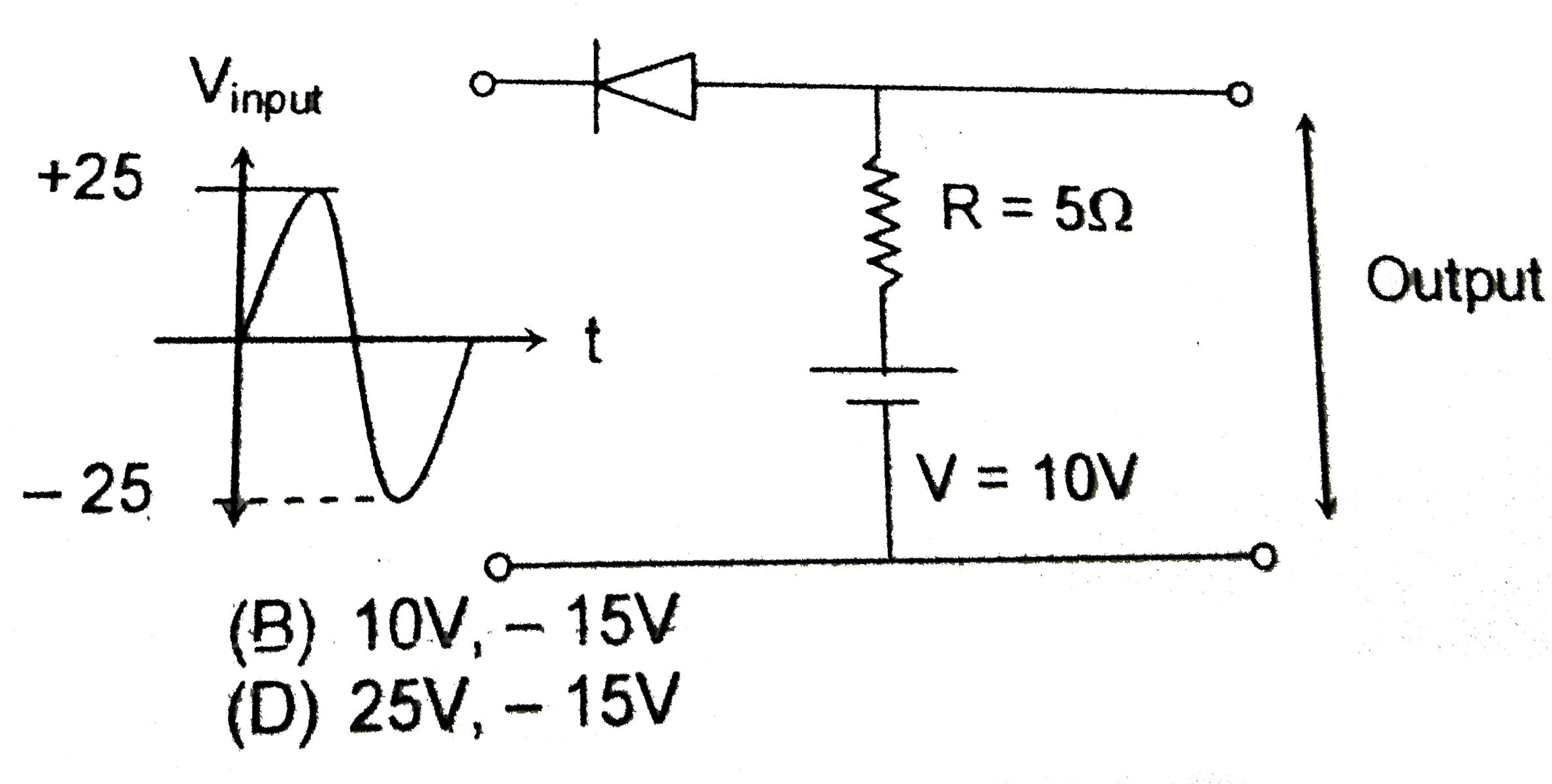
An ideal diode is connected in a circuit with resistance R=5Ω and V=10 volt as shown in figure maximum and minimum value of output voltage. When no load applied is (assume diode to be ideal)A10V, -25 VB10V, -15 VC25V,-25VD25V, -15V
An electric heater is designed to operate in 100V main with a power output of 1000W .When it is connected to a 25V source,power output is:
View SolutionIn the circuit What should be the value of r in ohm so that power developed in the resistor r will be maximum ?

View SolutionAn alternating e.m.f. 100 cos 100 t volt is connected in series to a resistance of 10 ohm and inductance 100mH. The phase difference between the current in the circuit and the e.m.f. is
View SolutionAn alternating e.m.f. 100 cos 100 t volt is connected in series to a resistance of 10 ohm and inductance 100mH. The phase difference between the current in the circuit and the e.m.f. is
View SolutionA coil of resistance 10Ω and an inductance 5H is connected to a 100 volt battery. Then energy stored in the coil is
View Solution
