In the shown figures (1) and (2), capacitors are in steady state. Charging batteries are removed a switches and are closed at time . The plot In I (I is the current in the resistor ) against time t the resitors and are shown in the figure. Choose the correct option (s)
(1) 
If must be equal to
If must be less than
If must be less than
is equal to
The correct Answer is:A, B, C
Step by step video, text & image solution for In the shown figures (1) and (2), capacitors are in steady state. Charging batteries are removed a switches S_(1) and S_(2) are closed at time t = 0. The plot In I (I is the current in the resistor ) against time t the resitors R_(1) and R_(2) are shown in the figure. Choose the correct option (s) (1) by Physics experts to help you in doubts & scoring excellent marks in Class 11 exams.
Similar Questions
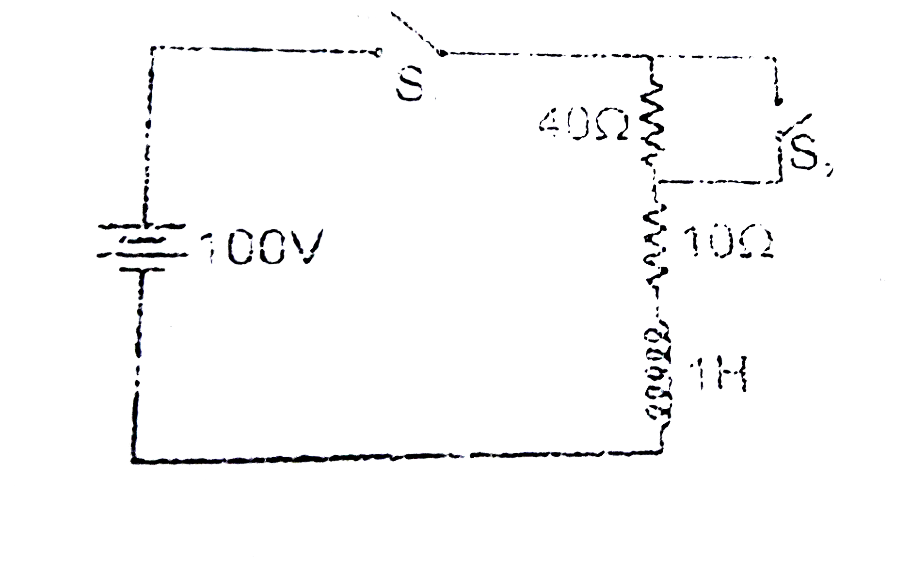
In the circuit diagram shown in the figure the switches S1 and S2 are closed at time t=0.After time t=(0.1)ln2sec, switch S2 is opened.The current in the circuit at time t=0.2n2sec is equal to x32amp.Find out value of x.
 View Solution
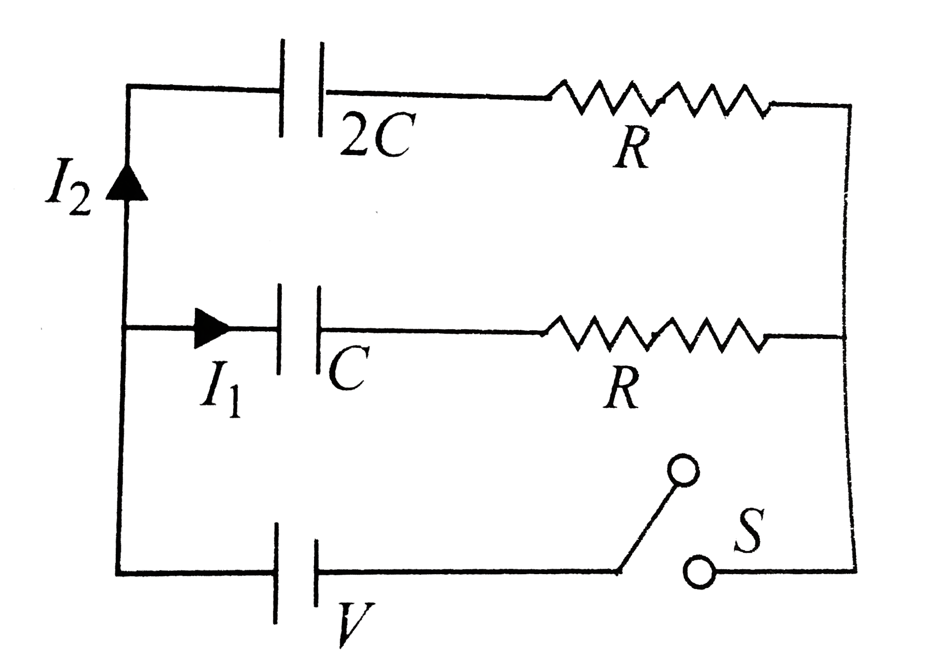
In the circuit shwon in fig. switch S is closed at time t = 0. Let I1andI2 be the currents at any finite time t, then the ratio I1/I2
 View Solution
Knowledge Check
- Question 1 - Select One
In the circuit shown in the figure, if switches S1 and S2 have been closed for a long time, then charge on the capacitor.
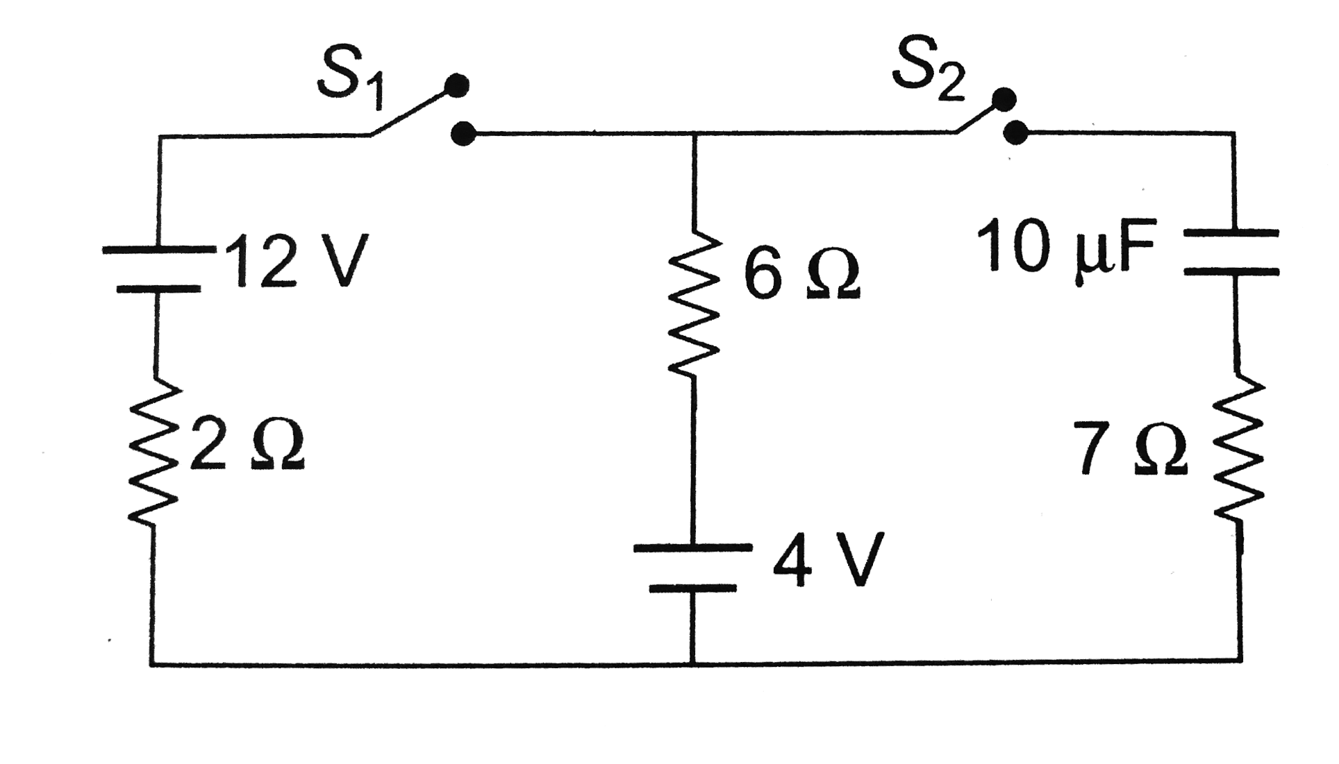 Ais 100μCBincreases to 200μC if one third of the gap of the capacitor's plates is filled with a dielectric (K=2) of same areaCboth (a) and (b) aboveDcharge on the capacitor remains unchanged if one third of the gap of the capacitor's plates is filled with a dielectric (K=2) of same area.
 - Question 2 - Select One
The switch S is closed in the circuit shown at time t=0 . The current in the resistor at t=0 and t=∞ are respectively .
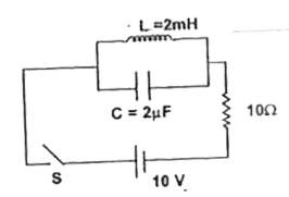 A0,0 AB1,0 AC0,1 AD1,1 A
 - Question 3 - Select One
In the circuit shown in the figure The steady state currents i1andi2 in the coils after the switch S is closed are
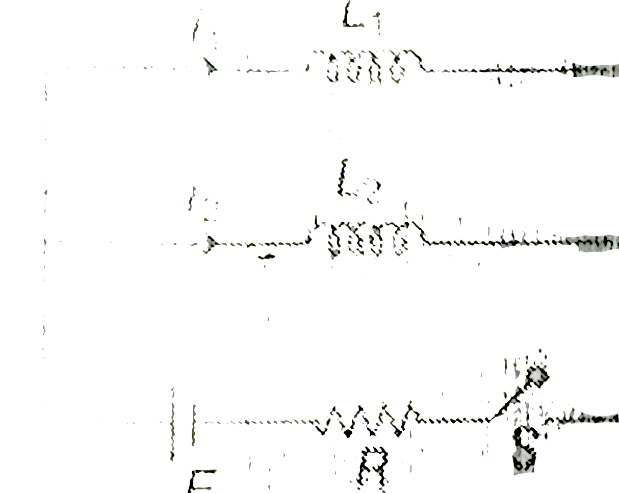 Ai1=EL2R(L1+L2)Bi1=EL1R(L1+L2)Ci2=EL2R(L1+L2)Di2=E√L1L2RL2
In the circuits (A) and (b) switches S1 and S2 are closed at t = 0 and are kept closed for a long time.The variation of current in the two circuits for t≥0 are roughly shown by figure (figures are schematic and not drawn to scale):
 View Solution
Two capacitors C1 and C2 are charged to same potential V, but with opposite polarity as shown in the figure. The switches S1 and S2 are then closed
 View Solution
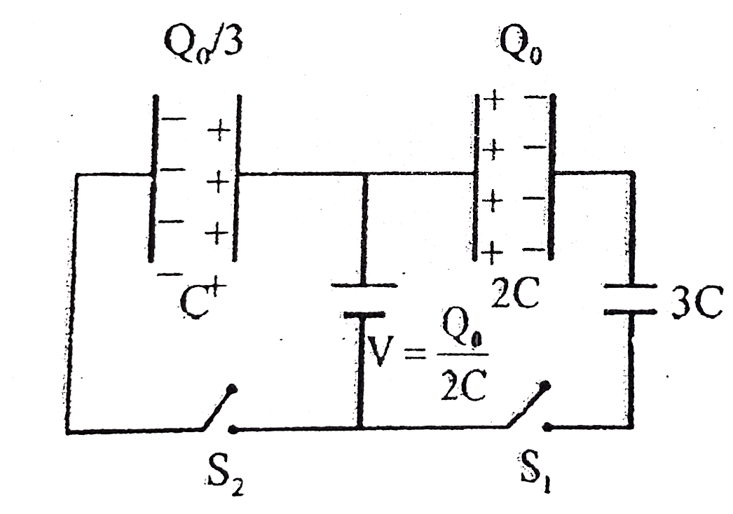
In the given circuit, the initial charges on the capacitors are shown in the figure. The charge flown through the switches S1andS2 respectively after closing the switches are
 View Solution
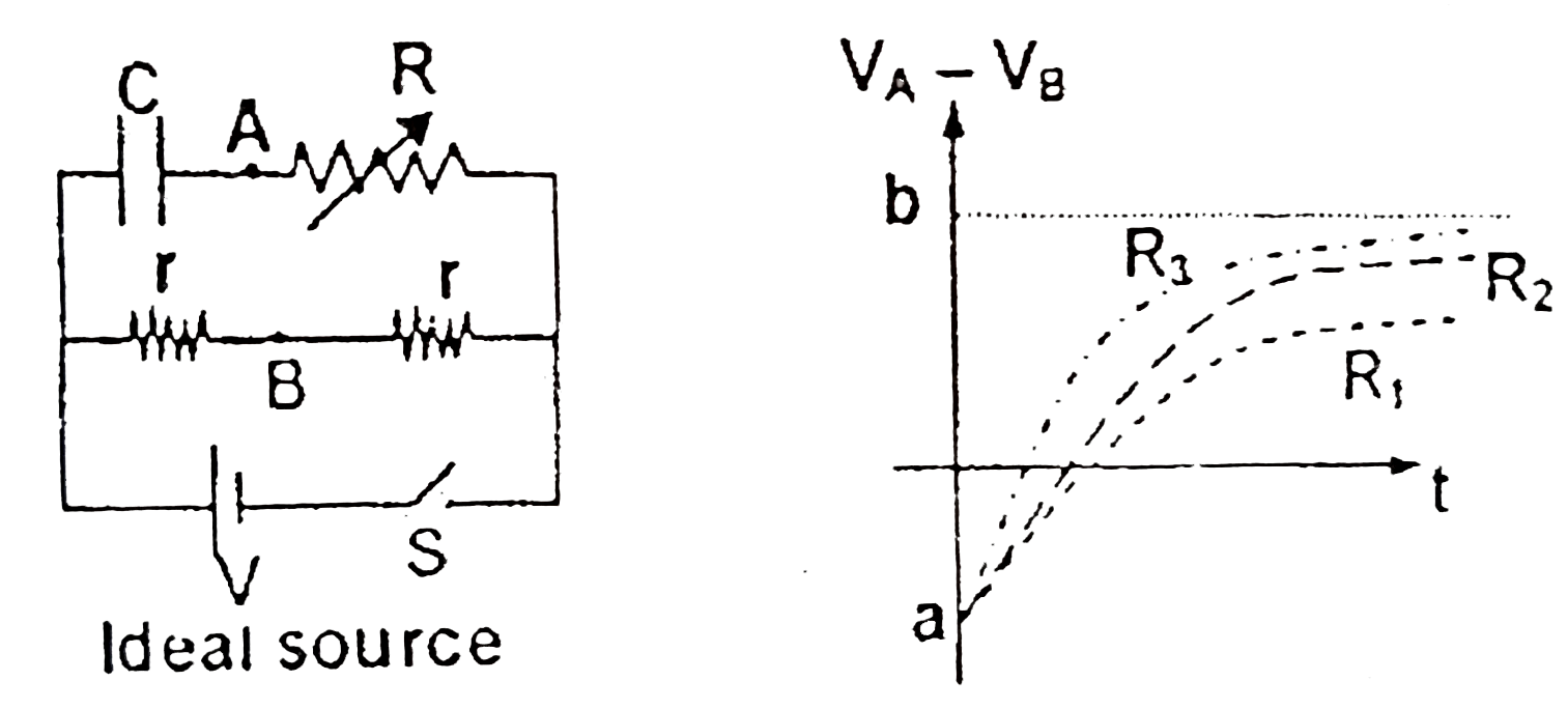
An uncharged capacitor C and a variable resistance R are connected to an ideal source and two resistors with the help of a switch at t=0 as shown in the figure. Initially capacitor is uncharged and switch S is closed at t=0sec. The graph between VA−VB for variable Resistor R for its three different values R1, R2, and R3 versus time is shown in the figure II. Choose the correct statement
 View Solution
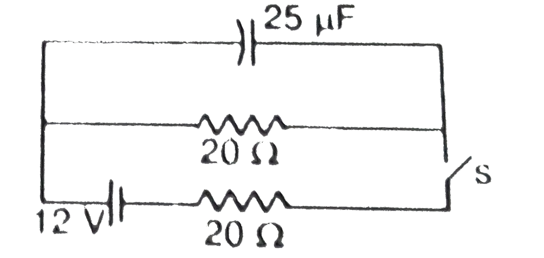
The switch S shown in figure is kept closed for a long time and then opened at t = 0, then the current in the middle 20Ω resistor at t=0.25 ms is :
 View Solution

