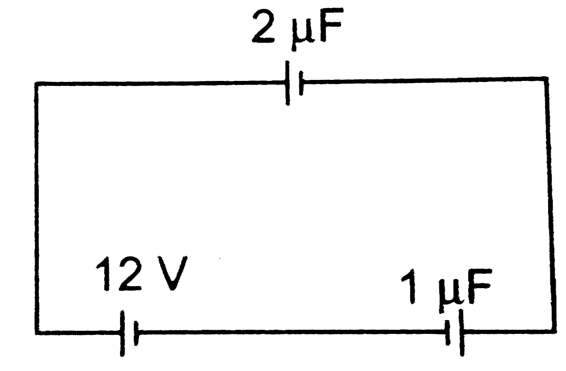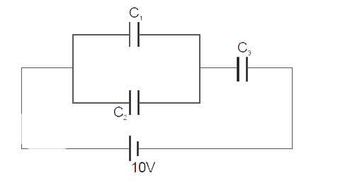
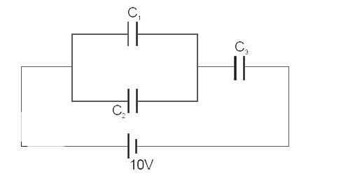
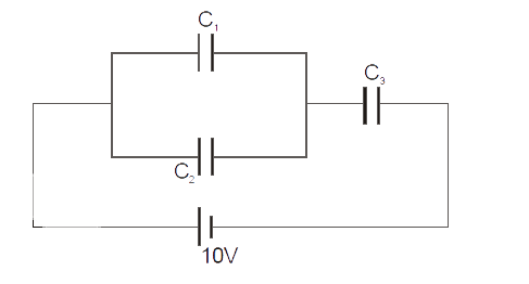
In the network shown in figure. C1=2.0μF,C2=6.0andC3=2.5μF. Determine (i) total capacitance, charge and energy of the system (ii) charges on separated capacitors (iii) potential differences across the separate capacitors.
Step by step video & image solution for In the network shown in figure. C_(1)=2.0muF,C_(2)=6.0 and C_(3)=2.5muF. Determine (i) total capacitance, charge and energy of the system (ii) charges on separated capacitors (iii) potential differences across the separate capacitors. by Physics experts to help you in doubts & scoring excellent marks in Class 12 exams.
Topper's Solved these Questions
- BOOK - SL ARORACHAPTER - CAPACITORSEXERCISE - Problem From Competitive Examinations17videos
CAPACITORS
- BOOK - SL ARORACHAPTER - ATOMS, NUCLEI AND MOLECULESEXERCISE - Problems For Self Practice87videos
ATOMS, NUCLEI AND MOLECULES
- BOOK - SL ARORACHAPTER - CHEMICAL EFFECT OF CURRENTEXERCISE - TYPE-B5videos
CHEMICAL EFFECT OF CURRENT
Similar Questions
Knowledge Check
- Question 1 - Select One
In the circuit shown in the figure, the potential difference across the 4.5μF capacitor is
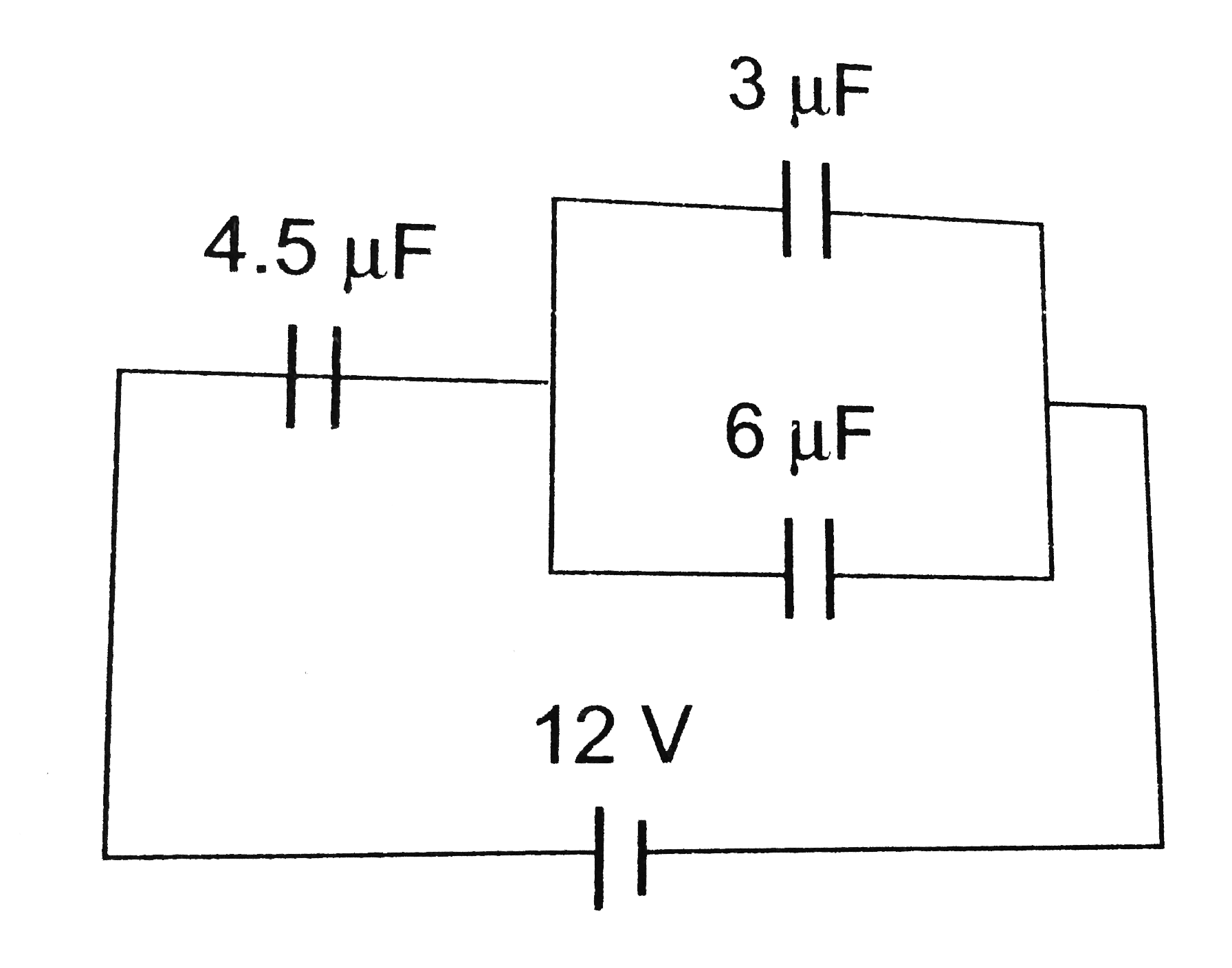 A83voltsB4 voltsC6 voltsD8 volts
 - Question 2 - Select One
In the given network capacitance, C1=10μF,C2=5μF and C3=4μF. What is the resultant capacitance between A and B?
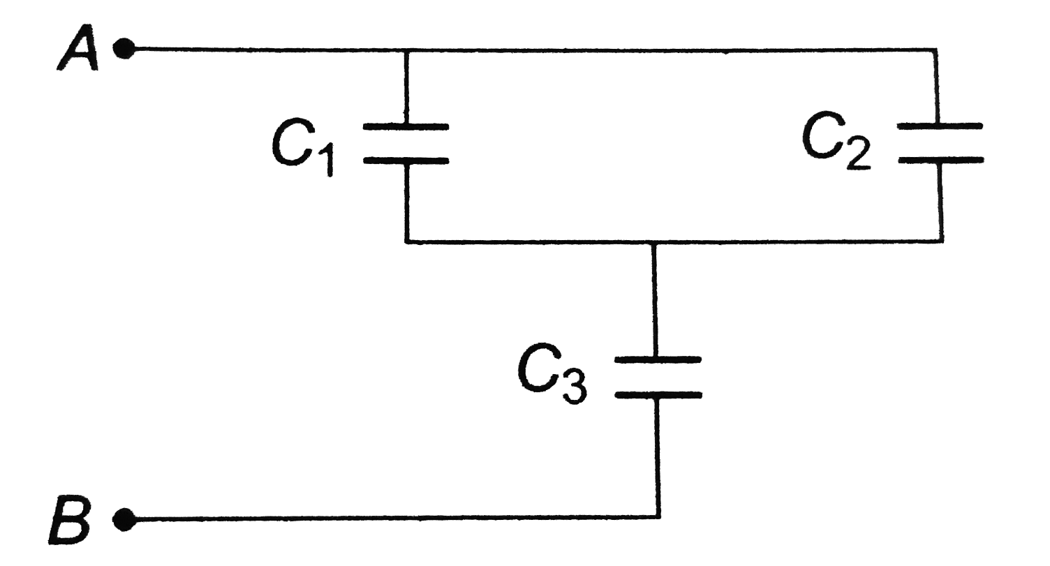 A2.2μFB3.2μFC1.2μFD4.7μF
 - Question 3 - Select One
A parallel plate capacitor of capacitance 1μF has a charge of +2μC on one of the plates and a charge of +4μC on the other. The potential difference developed across the capacitor is
A5VB2VC3VD1V
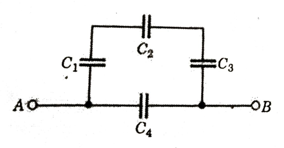
In the network shown in figure. C1=C2=C3=C4=10μF. Find th equivalent capacitance between the points A and B, what will be the charge on each capacitor?View SolutionIn the circuit shown the capacitors are C1=15μF,C2=10μFandC3=25μF. Find
the equivalent capacitance of the circuit.View Solution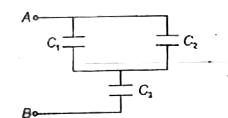
(a ) Find the equivalent capacitance of the combination shown in the figure ( a) when C1=2.0μF,C2=4.0μF and C3=3.0μF
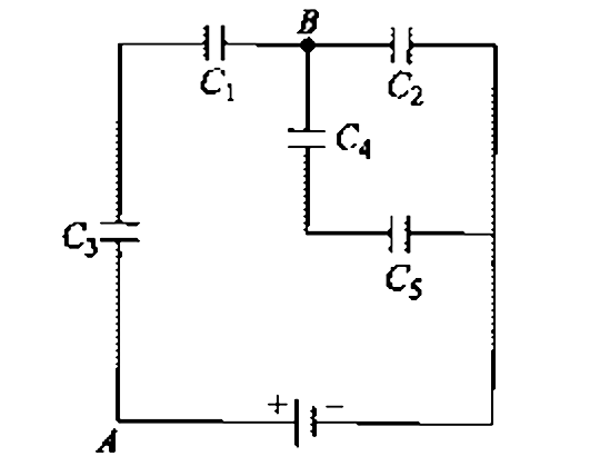
(b ) The input terminals A and B in figure (a) are connected to a battery of 12 V. Find the potential and the charge of each capacitor .View SolutionIn the circuit shown in figure C1=5μF,C2=29μC,C3=6μF,C4=3μF and C4=7μF. If in steady state potential difference between points A and B is 11 volt, calculate potential difference across C3.
 View Solution
In the circuit shown the capacitors are C1=15μF,C2=10μFandC3=25μF. Find
the potential difference across each capacitor.View Solution


