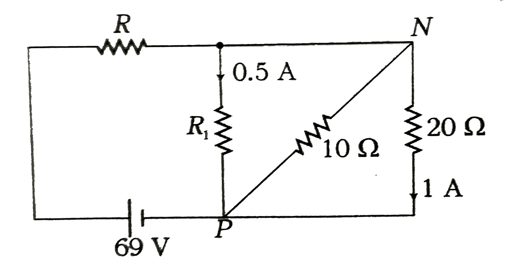
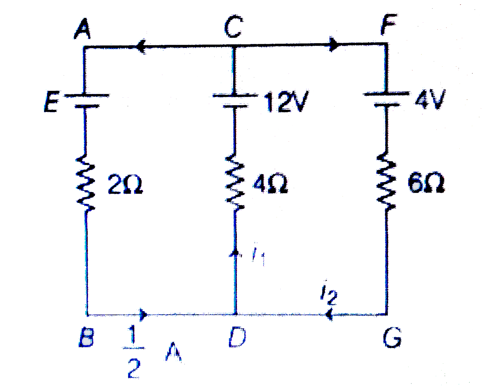
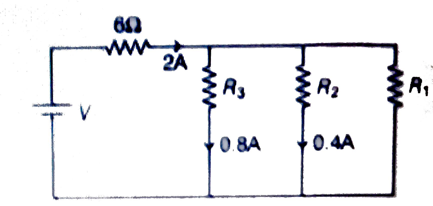
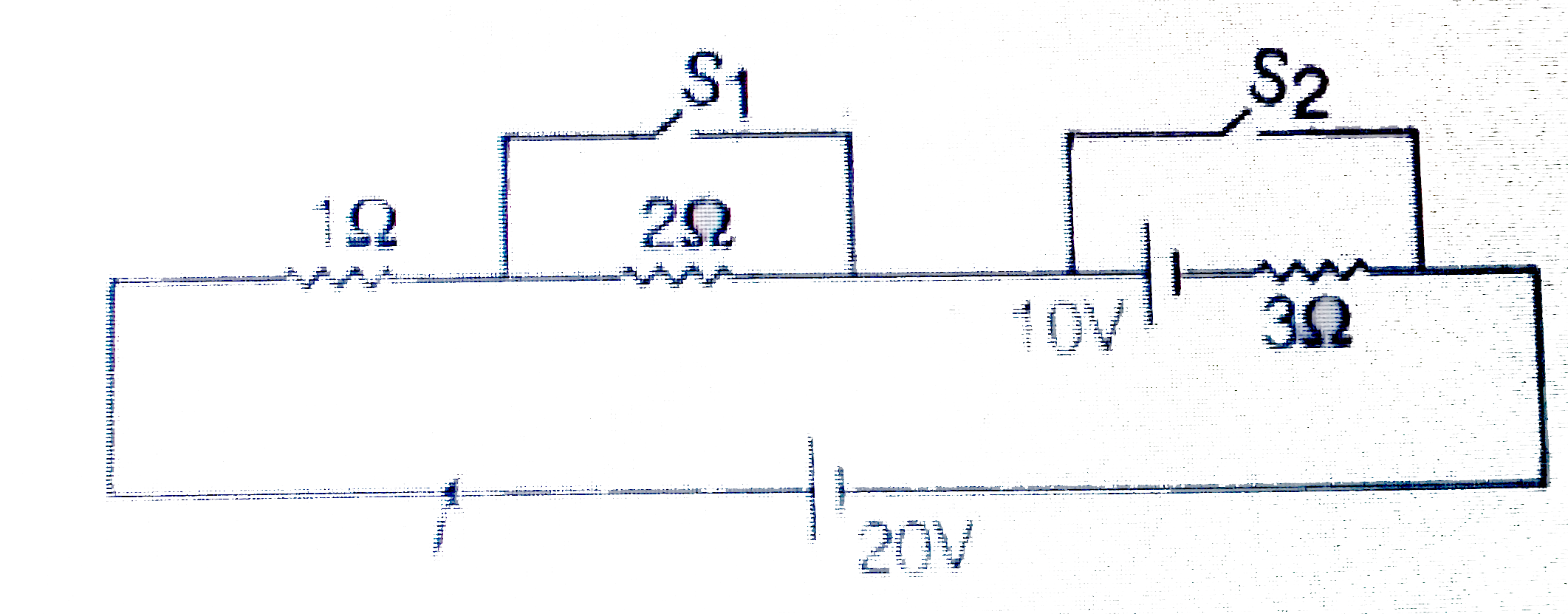
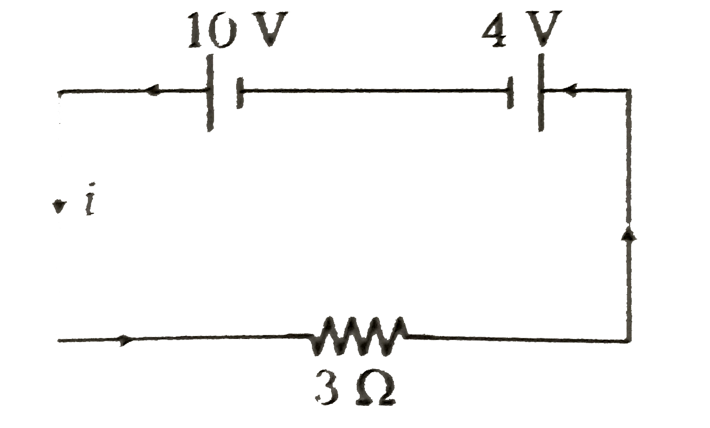
In the circuit shown in the following figure, find
Video Solution
|
Answer
Step by step video & image solution for In the circuit shown in the following figure, find by Physics experts to help you in doubts & scoring excellent marks in Class 12 exams.
Updated on:21/07/2023Topper's Solved these Questions
- CURRENT ELECTRICITYBOOK - DC PANDEYCHAPTER - CURRENT ELECTRICITYEXERCISE - Check point
70 Videos
- CURRENT ELECTRICITYBOOK - DC PANDEYCHAPTER - CURRENT ELECTRICITYEXERCISE - Taking it together
142 Videos
- CURRENT ELECTRICITYBOOK - DC PANDEYCHAPTER - CURRENT ELECTRICITYEXERCISE - Level 2 Subjective
13 Videos
- COMMUNICATION SYSTEMBOOK - DC PANDEYCHAPTER - COMMUNICATION SYSTEMEXERCISE - Subjective
11 Videos
- ELECTROMAGNETIC INDUCTIONBOOK - DC PANDEYCHAPTER - ELECTROMAGNETIC INDUCTIONEXERCISE - Medical entrances gallery
25 Videos
Similar Questions
Knowledge Check
For the circuit shown in the following figure,
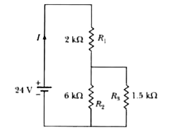 AThe current I through the battery is 7.5 mABThe potential difference across R3 is 18 VCRatio of powers dissipated in R1andR2 is 3DIf R1andR2 are interchanged, magnitude of the power dissipated in R3 will decrease by a factor of 9
For the circuit shown in the following figure.
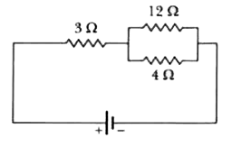 AThe heat dissipated in 4Ω resistance is more than that dissipated in 12Ω resistanceBMaximum heat is dissipated in 3Ω resistanceCThe heat dissipated in 12Ω resistance is more than that dissipated in 4Ω resistanceDThe power dissipated in 3Ω resistance is 18 W
For the circuit shown in the following figure, the
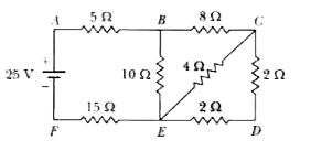 APotential difference between points B and E is 5 VBPotential difference between points A and B is 10 VCCurrent in the 4Ω resistor is 0.25ADCurrent in the 4Ω resistor is 0.5 A

