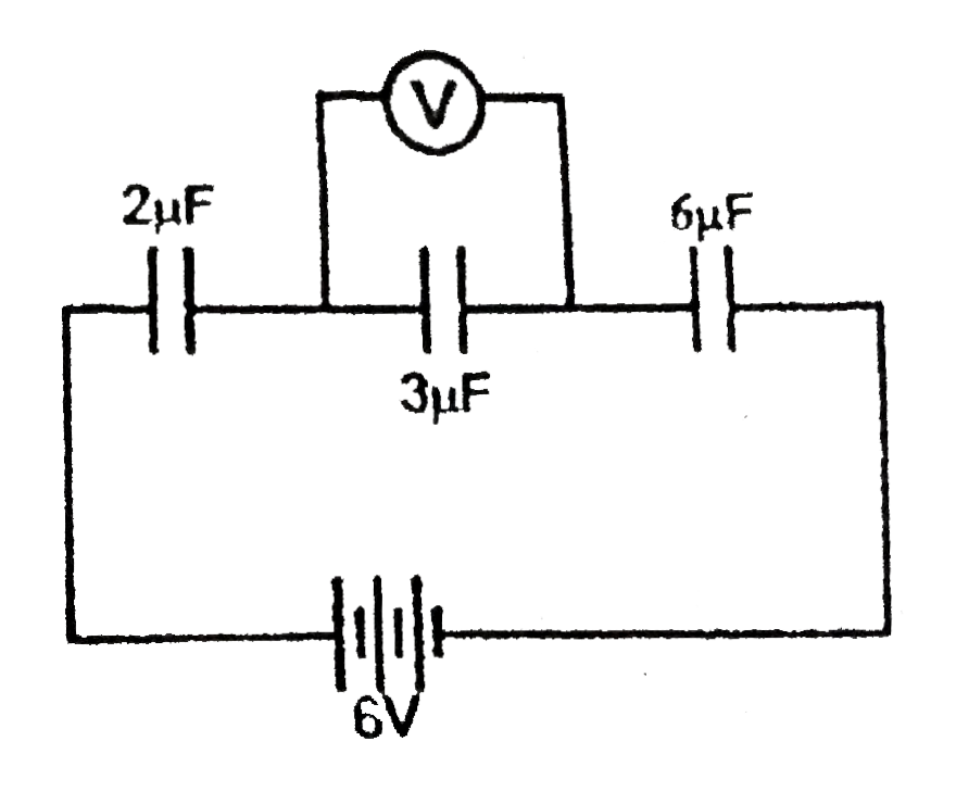
In the circuit shown in the figure, the voltmeter reading is
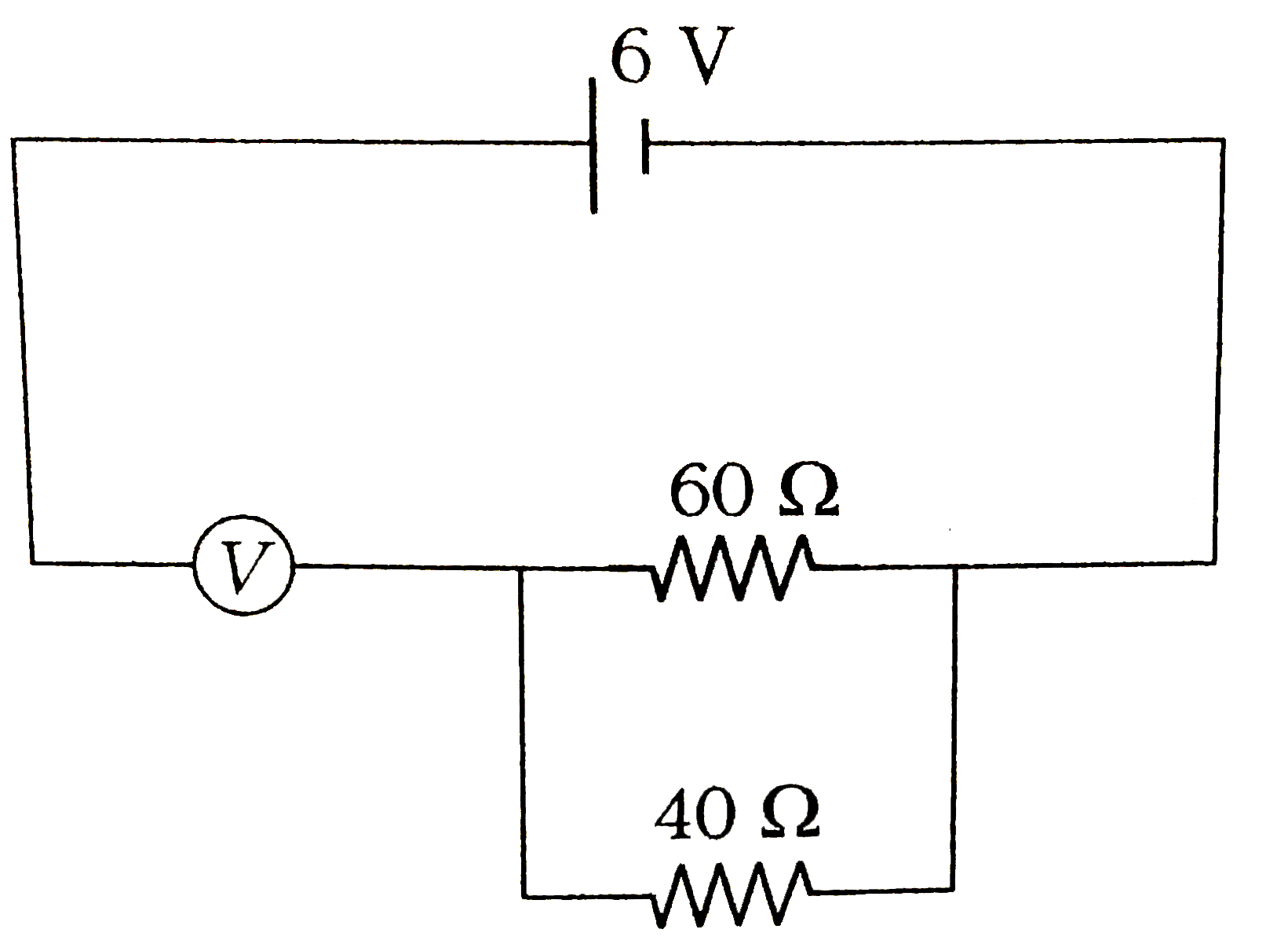
2.4V
3.4V
4.0V
6.0V
The correct Answer is:D
Step by step video, text & image solution for In the circuit shown in the figure, the voltmeter reading is by Physics experts to help you in doubts & scoring excellent marks in Class 12 exams.
Topper's Solved these Questions
- BOOK - DC PANDEYCHAPTER - CURRENT ELECTRICITYEXERCISE - Taking it together142videos
CURRENT ELECTRICITY
- BOOK - DC PANDEYCHAPTER - CURRENT ELECTRICITYEXERCISE - B. Assertion and reason18videos
CURRENT ELECTRICITY
- BOOK - DC PANDEYCHAPTER - CURRENT ELECTRICITYEXERCISE - Example61videos
CURRENT ELECTRICITY
- BOOK - DC PANDEYCHAPTER - COMMUNICATION SYSTEMEXERCISE - Subjective11videos
COMMUNICATION SYSTEM
- BOOK - DC PANDEYCHAPTER - ELECTROMAGNETIC INDUCTIONEXERCISE - Medical entrances gallery25videos
ELECTROMAGNETIC INDUCTION
Similar Questions
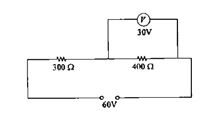
In the circuit shown in figure-3 .3 89, the voltmeter reads 30V when it is connected across 400Ω resistance. Calculate what the same voltmeter will read when it is connected across the 300Ω resistance.
 View Solution
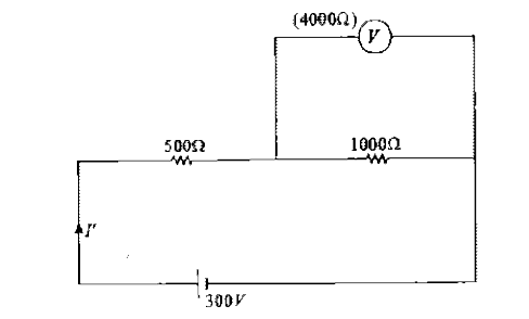
In the circuit shown in figure-3.387, the voltmeter is having a resistance 4000Ω. Find the percentage error in reading of this voltmeter.
 View Solution
Knowledge Check
- Question 1 - Select One
Is correct. In the circuit shown in the figure, the voltmeter reading would be.
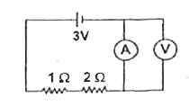 AO volt.B0.5 volt.C1 volt.D2 volt.
 - Question 2 - Select One
In the series circuit shown in the figure the voltmeter reading will be (all the meters are ideal).
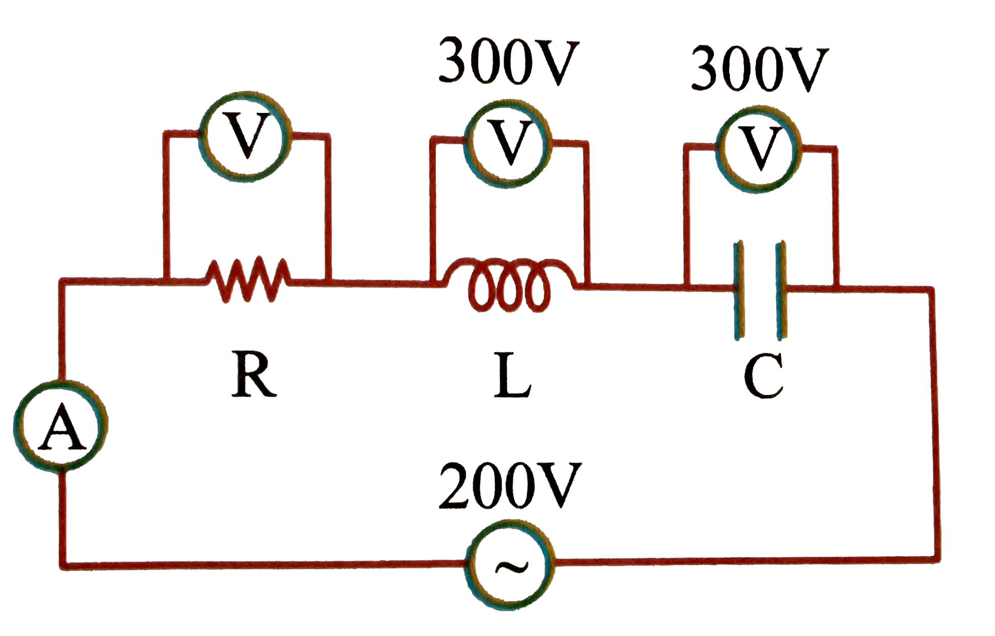 A300VB200VC100VD600V
 - Question 3 - Select One
An ammeter A, a voltmeter V and a resistance R are connected as shown in the figure. If the voltmeter reading is 1.6V and the ammeter reading is 0.4A, then R is
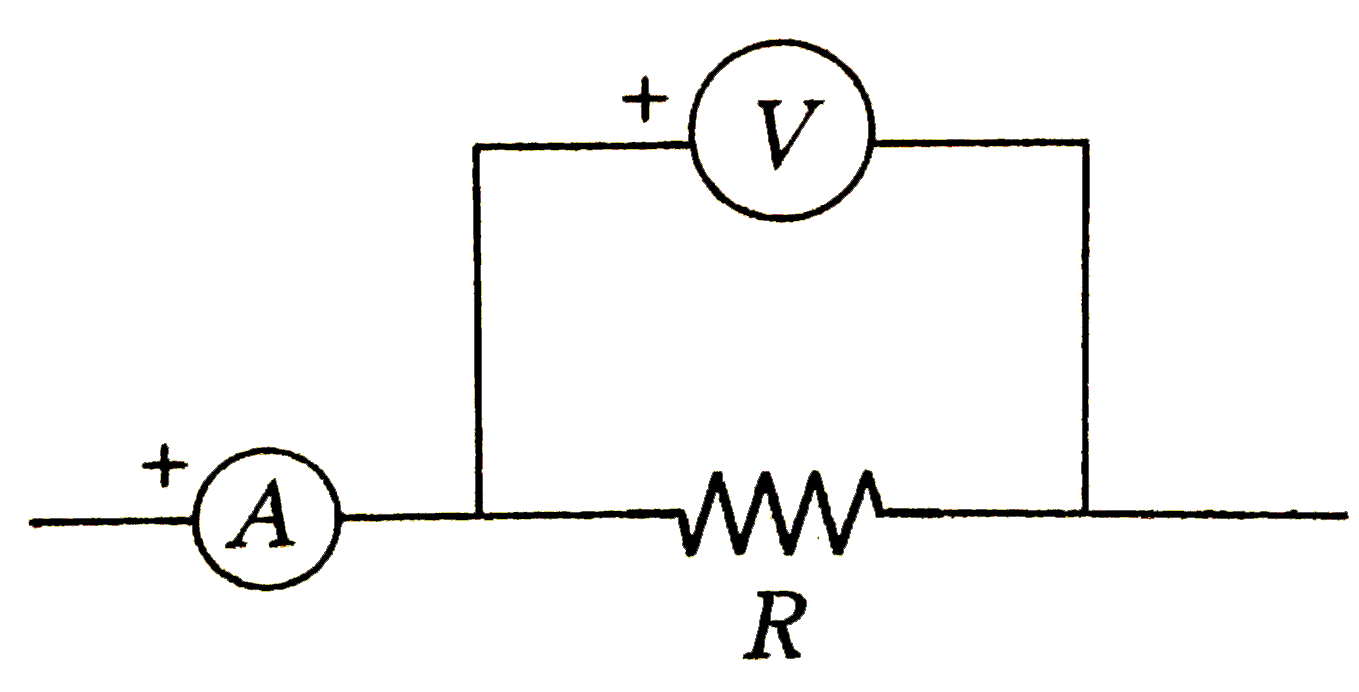 Aequal to 4ΩBgreater than 4ΩCless than 4ΩDbetween3Omegaand4Omega
State ohm's law.
In the circuit shown in figure, a voltmeter reads 30 volts when it is connected across 400 ohm resistance. Calculate what the same voltmeter will read when it is connected across the 300 ohm resistance.
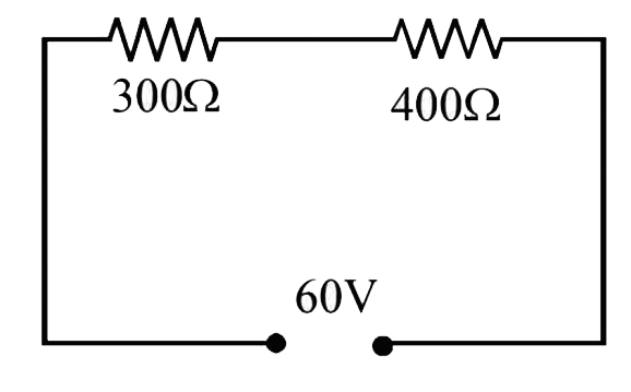 View Solution
In the circuit shown in figure, what will be the readings of voltmeter and ammeter?
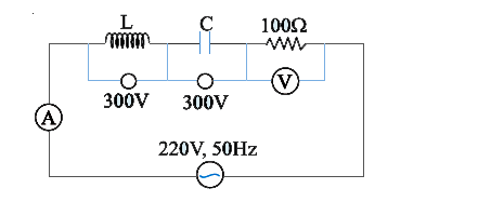 View Solution
In the combination shown in the figure, the ideal voltmeter reading will be
 View Solution
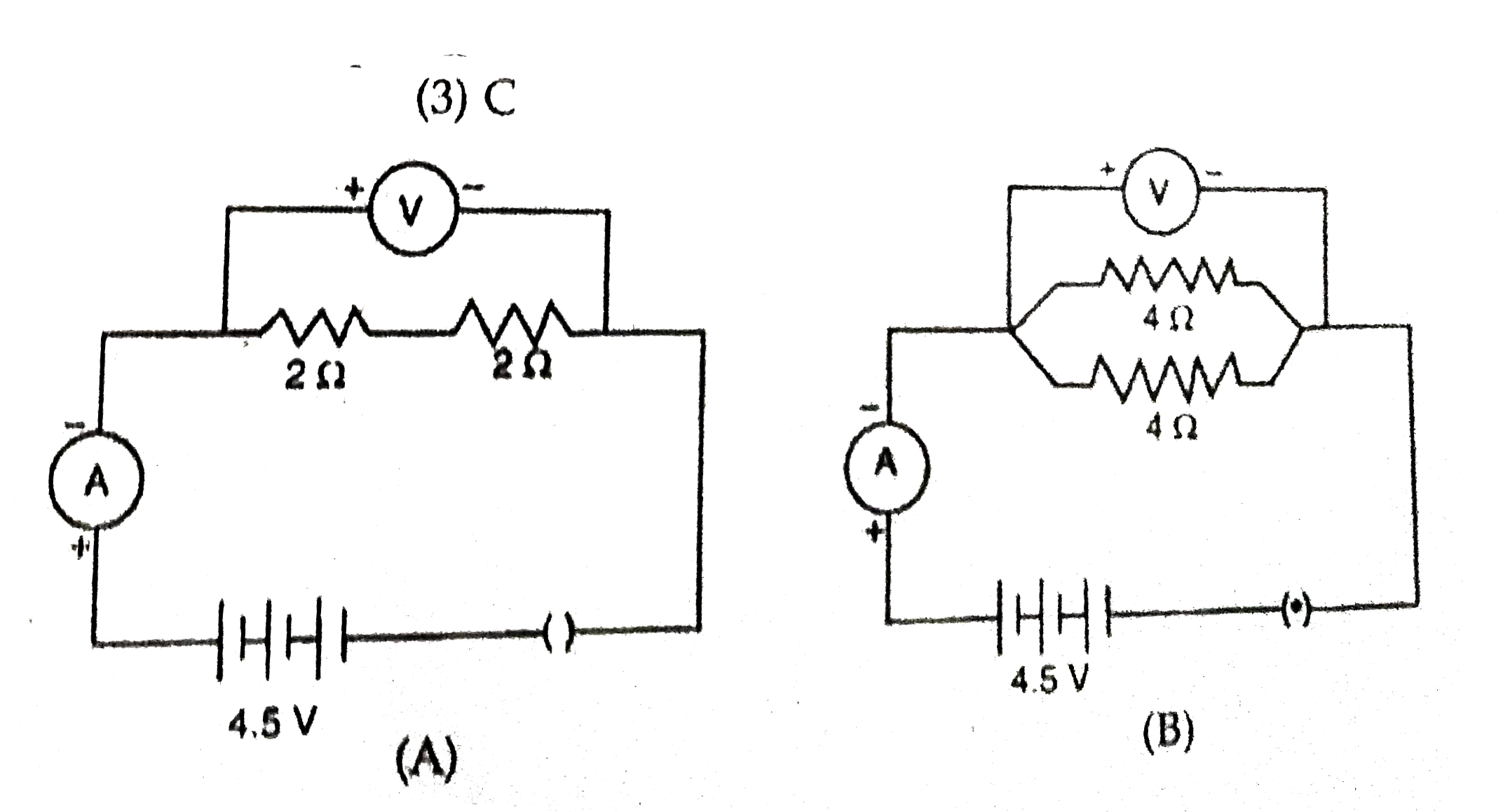
Consider the two circuits A and B given alongside :
In the circuits A and B shown here, the voltmeter reading would be :
 View Solution
In the circuit shown in figure, what will be the reading of the voltmeter ?
 View Solution

