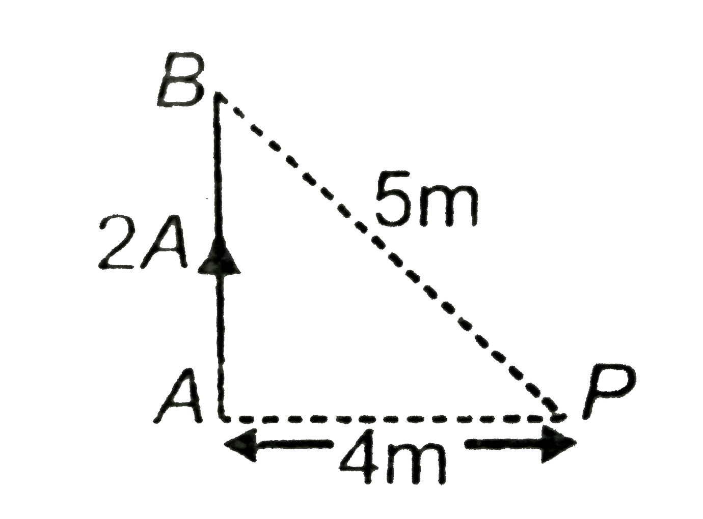
The adjacent figure shows, the cross-section of a long rod with its length perpendicular to the plane of the paper. It carries constant current flowing along its length. B1,B2,B3andB4 respectively respresent the magnetic fields due to the current in the rod at points 1,2,3and4 lying at different separations from the centre O as shown in the figure. which of the following shall hold true?

B1>B2≠0
B2>B3≠0
B1=B2=B3≠0
B2>B4≠0
The correct Answer is:d
Topper's Solved these Questions
- MAGNETIC FIELD AND FORCESBOOK - DC PANDEYCHAPTER - MAGNETIC FIELD AND FORCESEXERCISE - Match the following
4 Videos
- INTERFERENCE AND DIFFRACTION OF LIGHTBOOK - DC PANDEYCHAPTER - INTERFERENCE AND DIFFRACTION OF LIGHTEXERCISE - Level 2 Subjective
5 Videos
- MAGNETICSBOOK - DC PANDEYCHAPTER - MAGNETICSEXERCISE - MCQ_TYPE
1 Videos
Similar Questions
Knowledge Check
The figure shows the cross section of two long coaxial tubes carrying equal current I in opposites directions. If B1 and B2 are magnetic fields at point 1 and 2 as shown in figure then
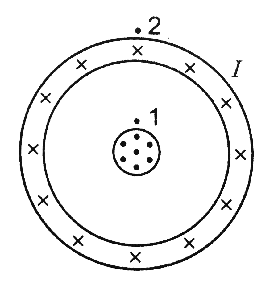 AB1≠0,B2=0BB1=0,B2=0CB1≠0,B2≠0DB1=0,B2≠0
A rod of length b moves with a constant velocity v in the magnetic field of a straight long conductor that carries a current I as shown in the below figure. The emf induced in the rod is
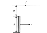 Aμ0Iv2πtan−1(ab)Bμ0Iv2πln(1+ab)Cμ0Iv√ab2π(a+b)Dμ0Iv(a+b)4πab
A rectangular loop of conductor of length a and breadtlı b carrying current / is shown in the figure. The magnetic field at the centre o of the loop is
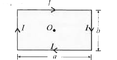 Aμ0(a+b)2π√a2+b2Bμ0Iab2π√a2+b2Cμ0(a+b)π√a2+b2D2μ0(a2+b2)πab
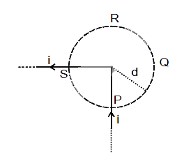
Figures shows a long wire bent at the middle to form a right angle. The magnitudes of the magnetic fields at the points P, Q, R and S are B1,B2,B3,B4 respectively. The wire and the circumference of circle are coplanar. Relation between B1,B2,B3,B4 are
View SolutionThe figure shows three straight current carrying conductors having current I1,I2 and I3 respectively. Calculate line integral of magnetic induction field →B along the closed path ABCDEFA

View SolutionThe figure shows the cross section of two long coaxial tubes carrying equal current I in opposites directions. If B1 and B2 are magnetic fields at point 1 and 2 as shown in figure then

View SolutionIn the figure shown as uniform magnetic field |B|=0.5T is perpendicular to the plane of circuit. The sliding rod of length l=0.25m moves uniformly with constant speed v=4ms−1. If the resistance of the sllides is 2Ω, then the current flowing through the sliding rod is
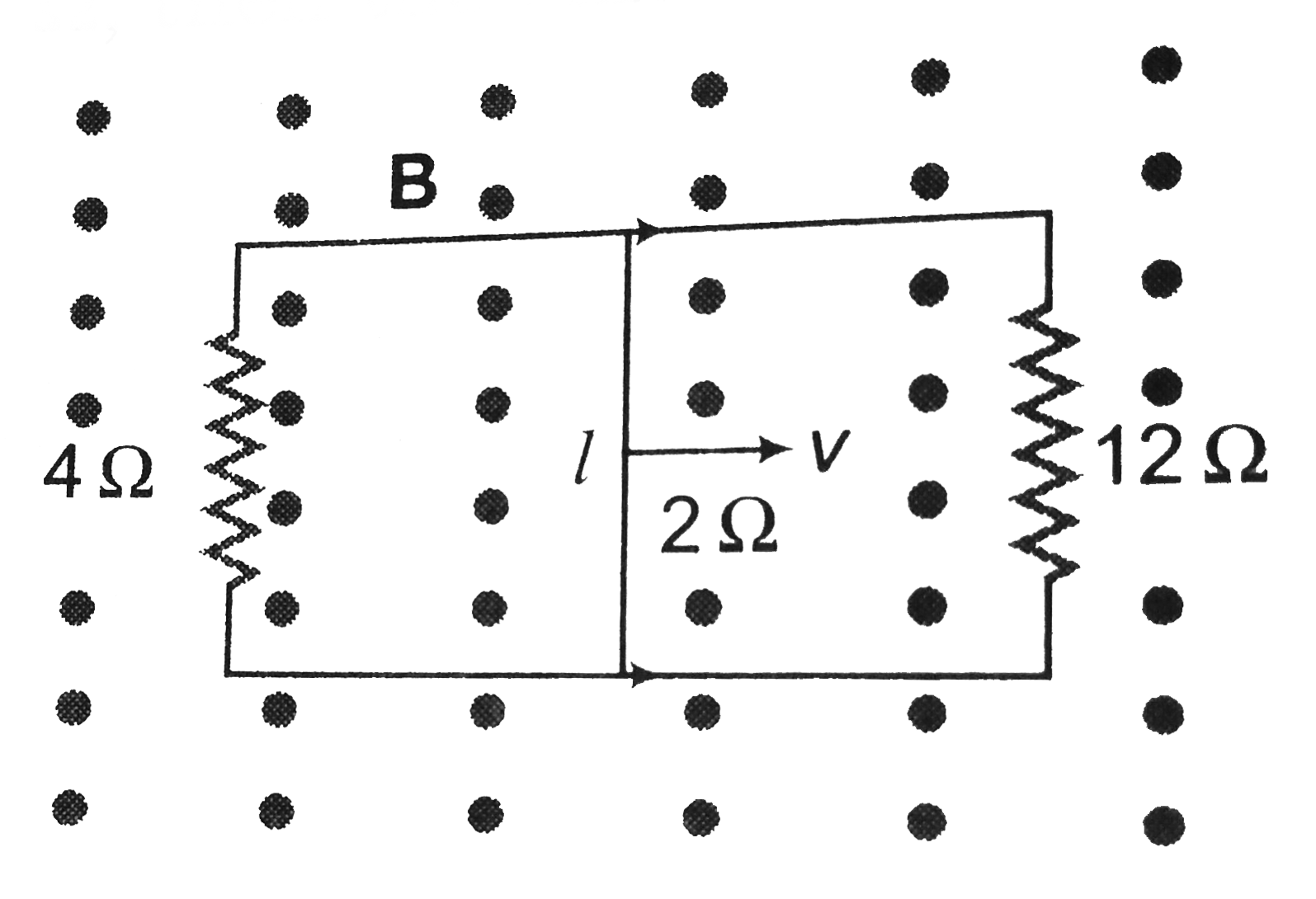
View SolutionIn the figure shown as uniform magnetic field |B|=0.5T is perpendicular to the plane of circuit. The sliding rod of length l=0.25m moves uniformly with constant speed v=4ms−1. If the resistance of the sllides is 2Ω, then the current flowing through the sliding rod is

View Solution

