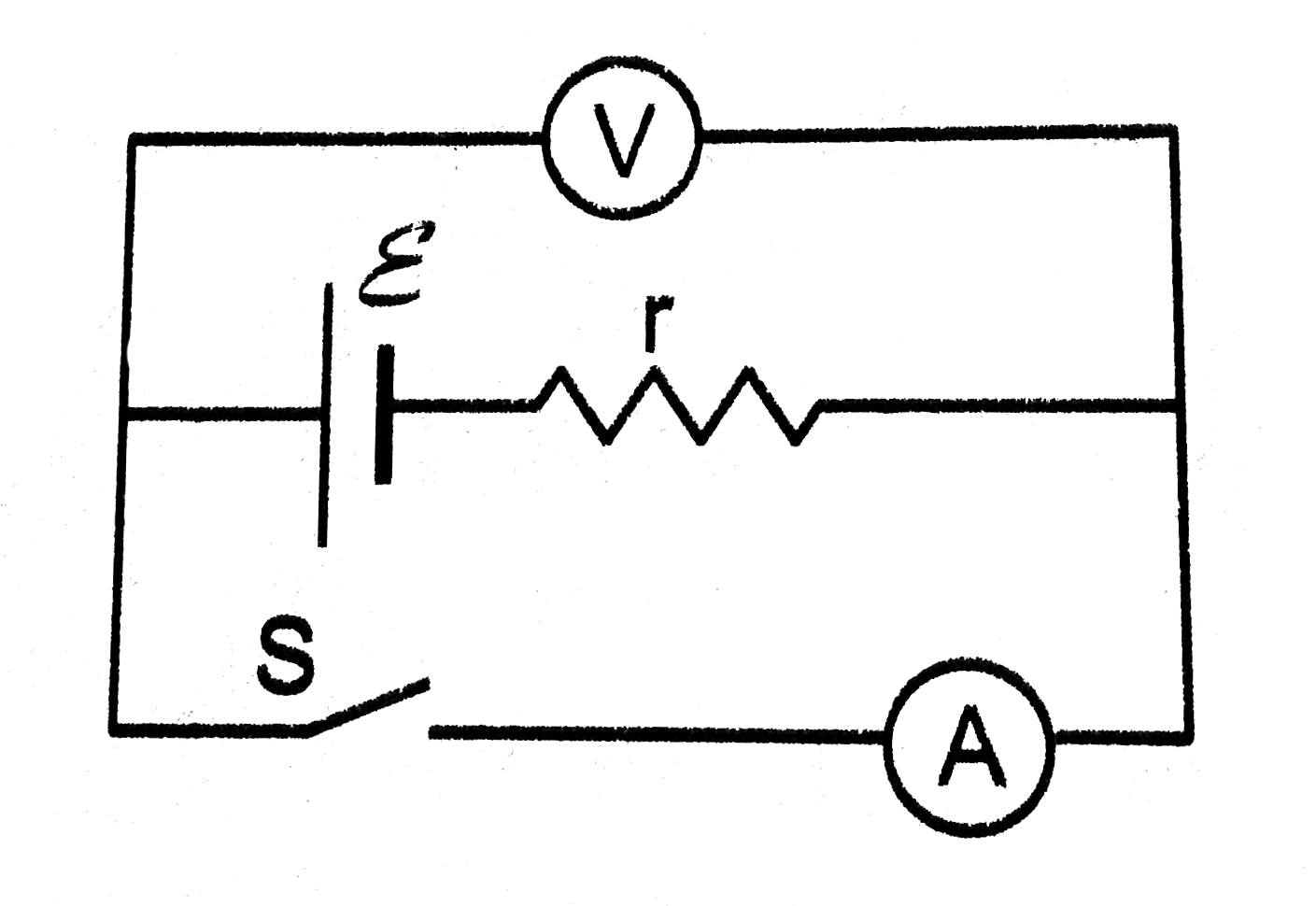
In the circuit shown in Fig. 4.25, the voltmeter reads 1.5 V, when the key is open. When the key is closed, the voltmeter reads 1.35 V and ammeter reads 1.5 A. Find the emf and the internal resistance of the cell.
Step by step video & image solution for In the circuit shown in Fig. 4.25, the voltmeter reads 1.5 V, when the key is open. When the key is closed, the voltmeter reads 1.35 V and ammeter reads 1.5 A. Find the emf and the internal resistance of the cell. by Physics experts to help you in doubts & scoring excellent marks in Class 12 exams.
Updated on:21/07/2023Topper's Solved these Questions
- CURRENT ELECTRICITYBOOK - SL ARORACHAPTER - CURRENT ELECTRICITYEXERCISE - Problems From Competitive
18 Videos
- CURRENT ELECTRICITYBOOK - SL ARORACHAPTER - CURRENT ELECTRICITYEXERCISE - Problems For Self
101 Videos
- CHEMICAL EFFECT OF CURRENTBOOK - SL ARORACHAPTER - CHEMICAL EFFECT OF CURRENTEXERCISE - TYPE-B
5 Videos
- ELECTRIC POTENTIAL AND ELECTRIC FLUXBOOK - SL ARORACHAPTER - ELECTRIC POTENTIAL AND ELECTRIC FLUXEXERCISE - Problems for self practive
61 Videos
Similar Questions
Shown an arrangement to measure the emf (ε)and internal resistance r of a battery. The voltmeter has a very high resistance and the ammeter also has some resistance.The voltmeter reads 1.52 V when the switch S is open.When the switch is closed the voltmeter reading drops to 1.45 V and the ammeter read 1.0A Find the emf and the internal resistance of the battery.
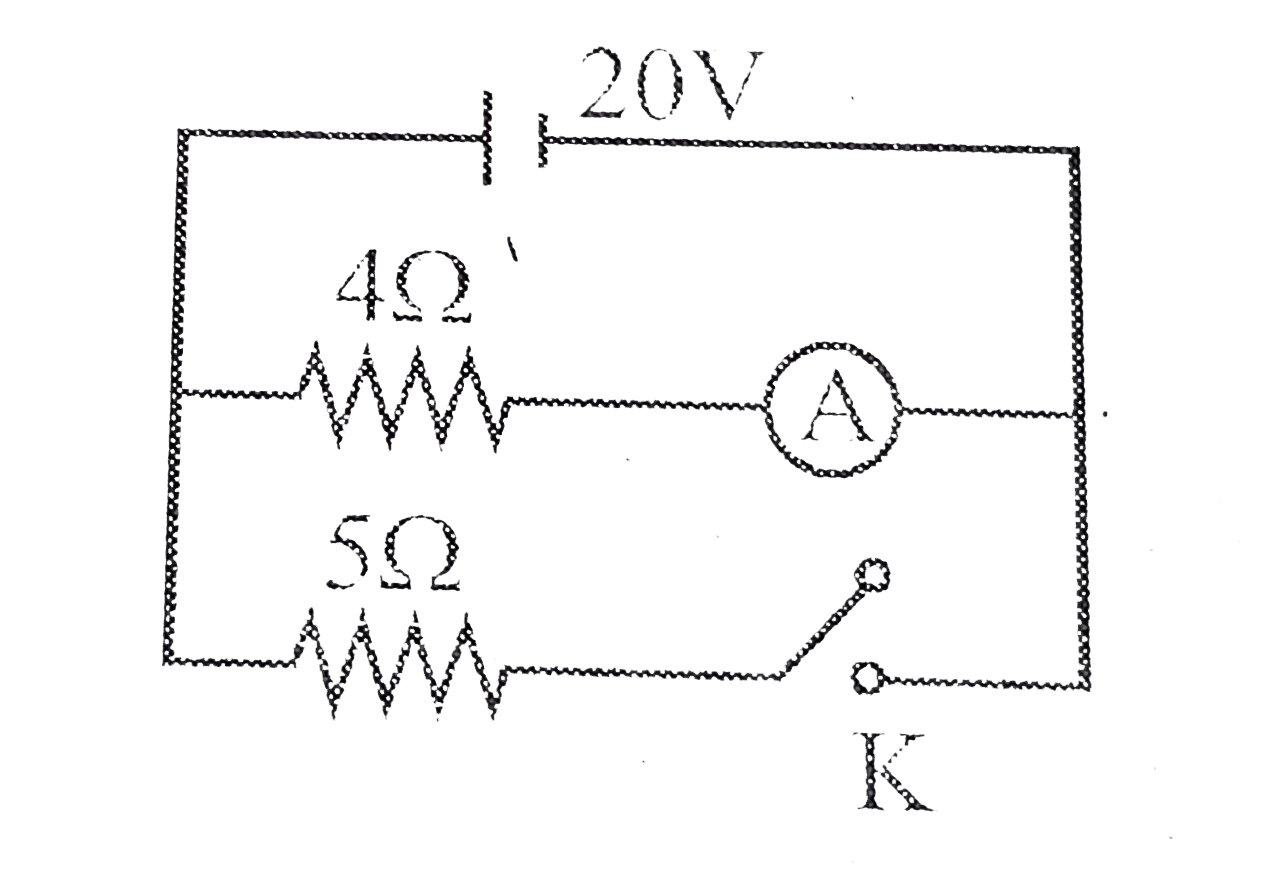
View SolutionIn the given figure when the key is open the ammeter reading is 5 amp. What will be the ammeter reading when the key is closed
View Solution
Knowledge Check
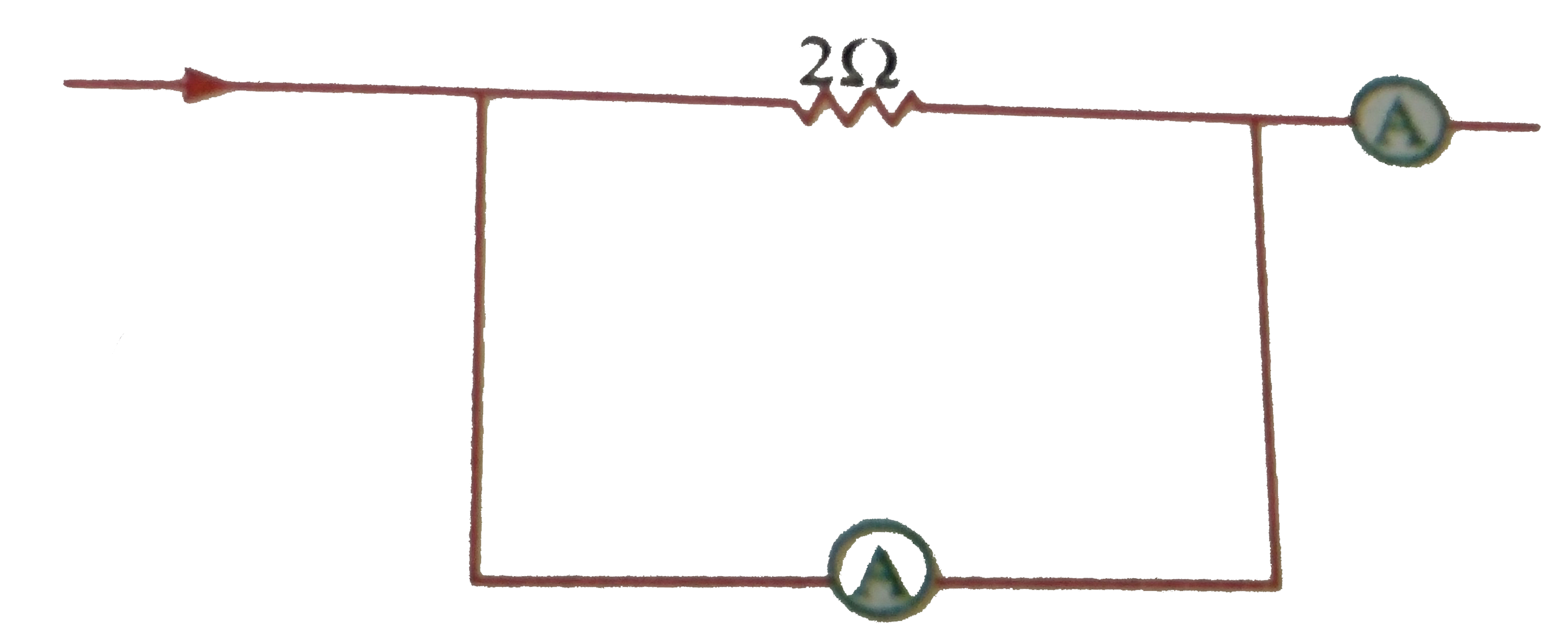
If the voltmeter reads 0.2 V and the ammeter reads 0.101A, the resistance of the voltmeter is (in ohm)A500B1000C200D400In the circuit shown in Fig. 6.50, an idel ammeter and an ideal voltmeter are used. Whan the key is open, the voltmeter reads 1.53V. When the key is closed, the ammeter reads 1.0A and the voltmeter reads 1.03V. The resistance R is
 A0.5ΩB1.03ΩC1.53ΩD1.53Ω
In the circuit figure, the voltmeter reads 30 V. The resistance of the voltmeter is
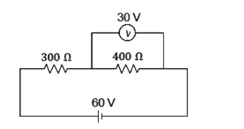 A1200ΩB700ΩC400ΩD300Ω
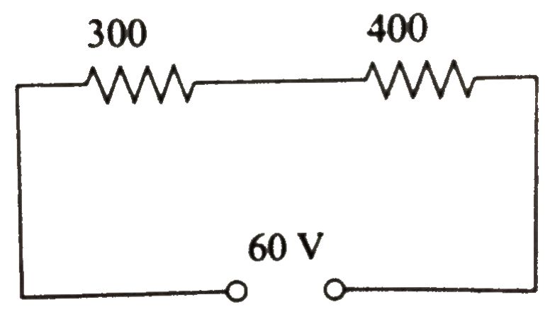
In the circuit diagram shown in Fig. 4.53, a voltmeter reads 30 V when connected across 400Ω resistance. Calculate what the same voltmeter reads when it is connected across 300Ω resistance.
View SolutionIn the circuit shows in Fig. 6.22, a voltmeter reads 30V when it is connected across a 400ω resistance. Calculate what the same voltmeter would read when it is connected across the 300Ω resistance.
View SolutionIf resistance of voltmeter is 10000Ω and resistance of ammeter is 2Ω then find R when voltmeter reads 12 V and ammeter reads 0.1 A
View SolutionIn the circuit shown below, the ammeter A reads 5 A and the voltmeter V reads 20 V The correct value of resistance R is

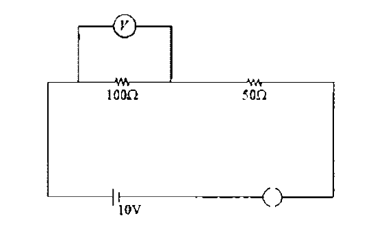
View SolutionIn the given circuit, the voltmeter reads SV. The resistance of the voltmeter is :
View Solution
