Two capacitors C1 and C2 are connected in a circuit as shown in figure. The potential difference (VA−VB) is
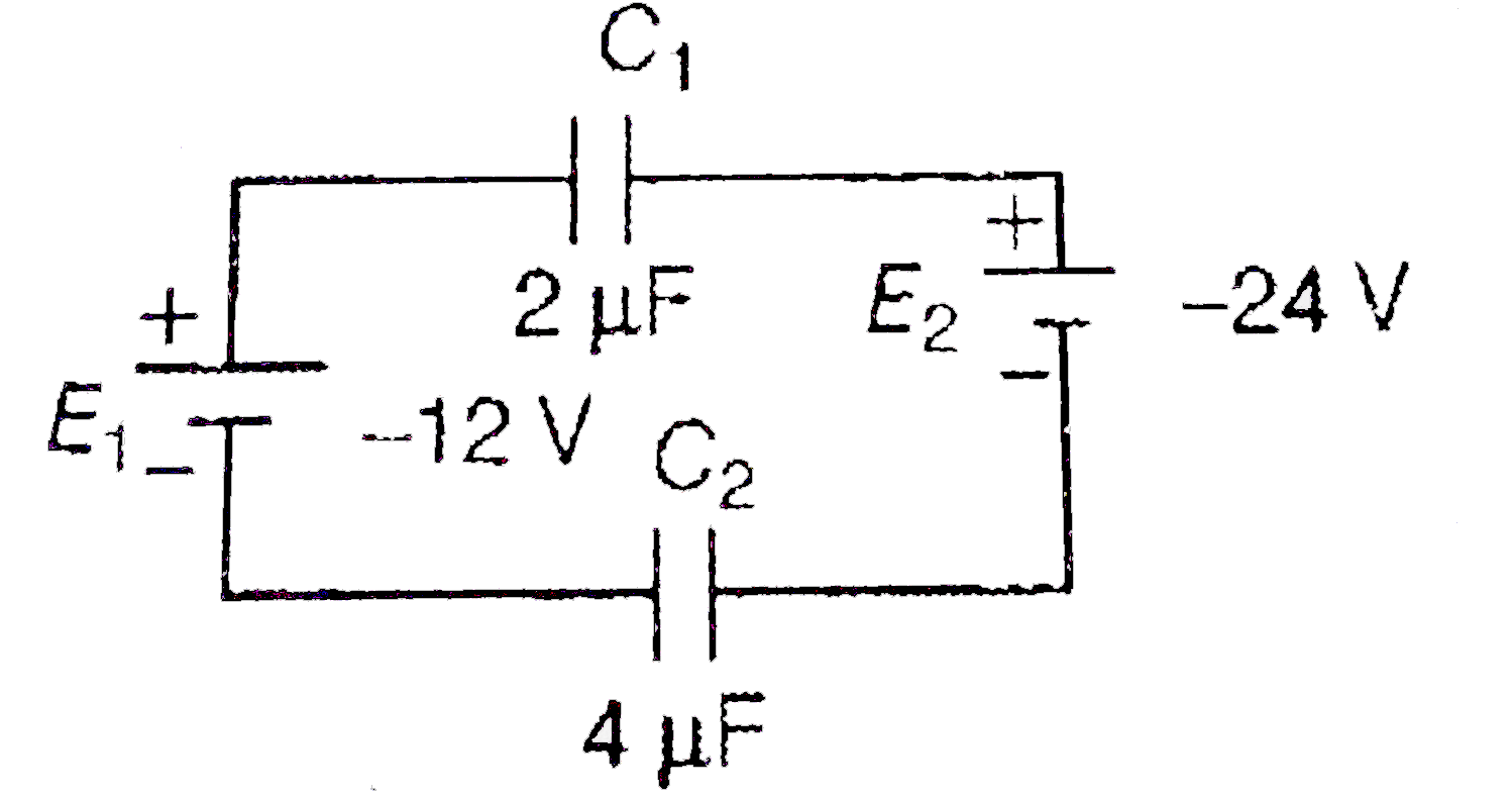
A
8V
B
−8V
C
12V
D
12V
Video Solution
Text Solution
The correct Answer is:B
Consider the diagram below going through the path shown
12−VA+VB−24+VD−VC=0
⇒VA−VB=12+VD−VC−24=−12+(Q4μF)
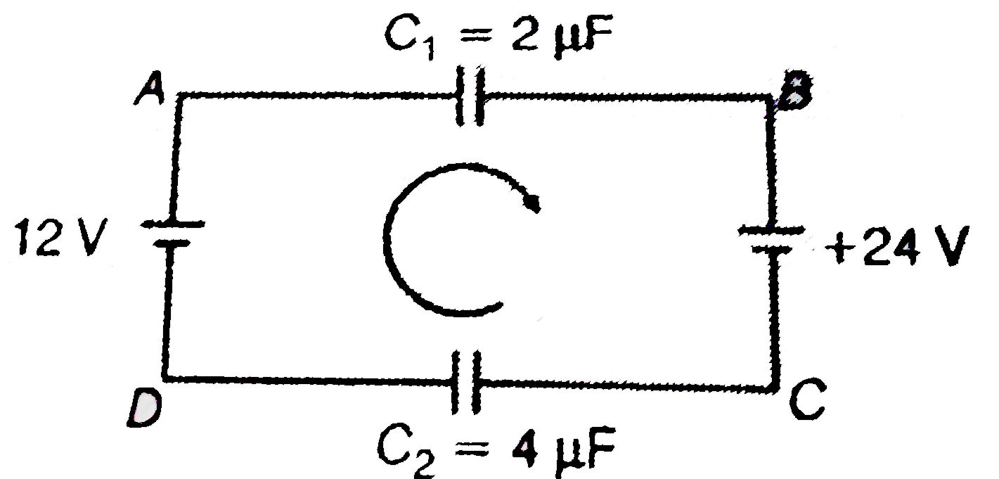
⇒−Q2μF=−12+Q4μF⇒Q[12+14]=12μC
⇒Q=12×86μC=16μC
VA−VB=−QC1=−16μC2μF=−8V
|
Updated on:21/07/2023
Topper's Solved these Questions
Similar Questions
Knowledge Check
- Question 1 - Select One
In the part of a circuit shown in figure, the potential different
(VG−VH) between points G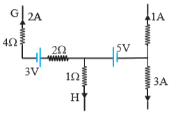 A0VB15VC21VD3V
 - Question 2 - Select One
In the circuit shown, what is the potential difference VPQ?
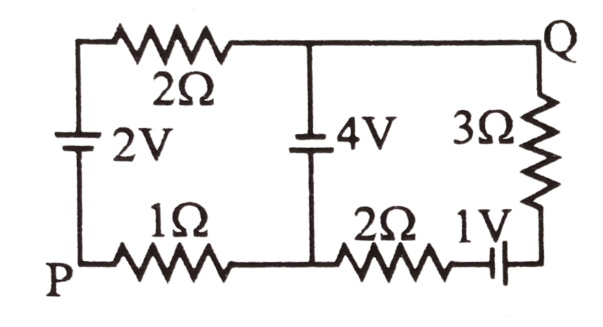 A+3VB+2VC−2VDnone
 - Question 3 - Select One
In the circuit shown, what is the potential different VPQ ?
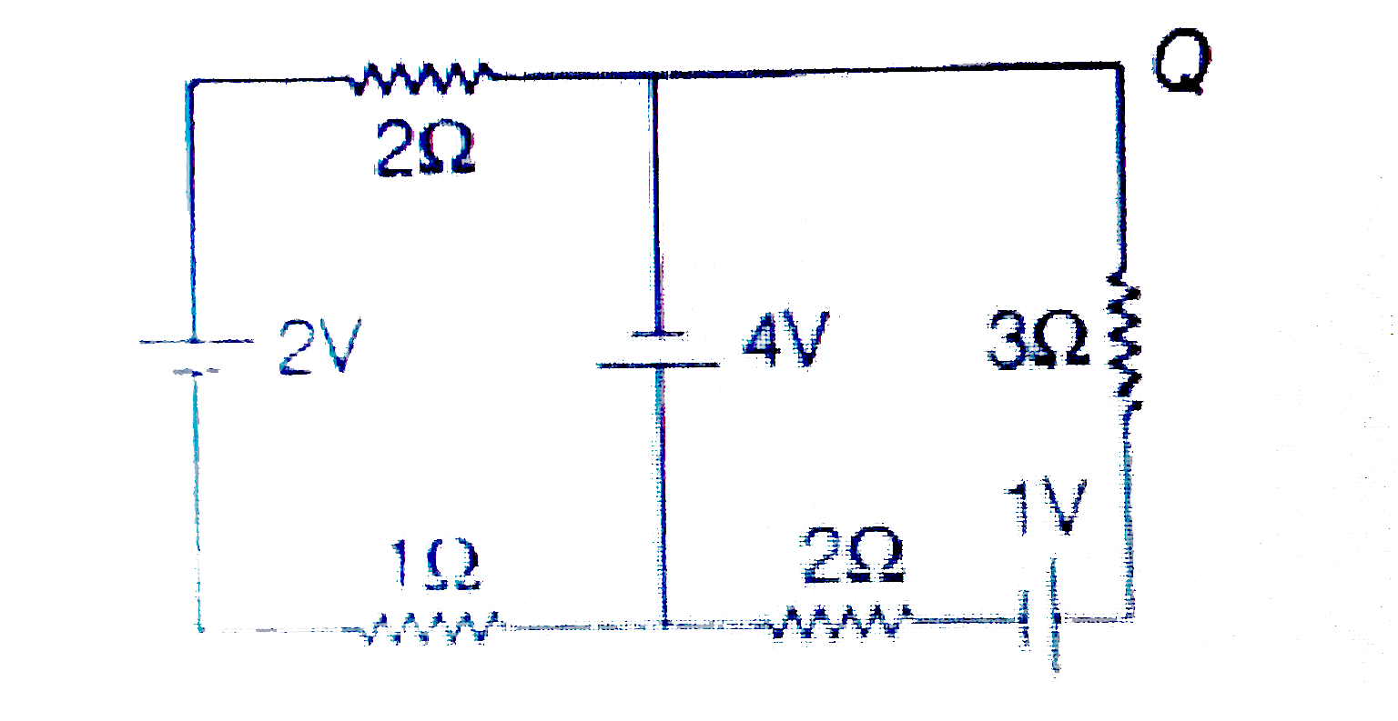 A+3VB+2VC−2VDNone of these
Four capacitors C1,C2,C3 and C4 are connected as shown in figure.If potential difference between points A and B is zero, then
View SolutionResistances of 6Ω each are connected in the manner shown in the following figure. The potential difference Vp−Vq is
 View Solution
Three capacitors C1,C2 and C3 are connected as shown in, The potentials of P,Q, and R are V1,V2, and V3, respectively. Find the potential V0 at the functionO.
 .View Solution
In the part of a circuit branch shown in figure-5.304 the potential difference Vab at t=1s is:
 View Solution
A circuit shown in the figure consists of a battery of emf 10V and two capacitance C1 and C2 of capacitances 1.0μF and 2.0μF respectively. The potential difference VA−VB is 5V
 View Solution


