Write the truth table for a NAND gate as given in Fig.9. Hence identify the exact logic operation carried out by this circuit.

A acts as the two inputs of the NAND gate and Y is the output, as shown in the following figure. 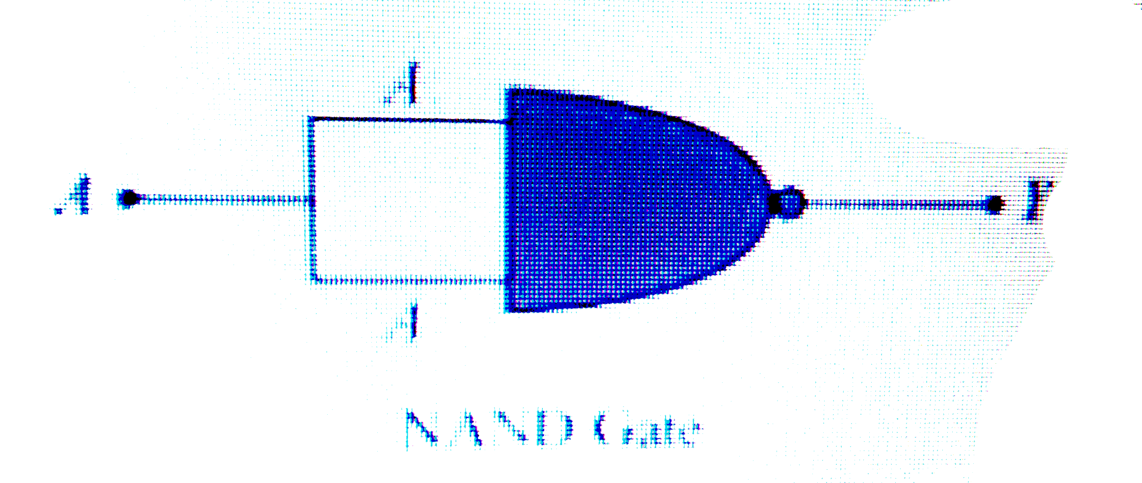
Hence, the output can be written as:
Y=¯¯¯¯¯¯¯¯A.A=¯¯¯A+¯¯¯A=¯¯¯A
The truth table for equation (i) can be drawn as:
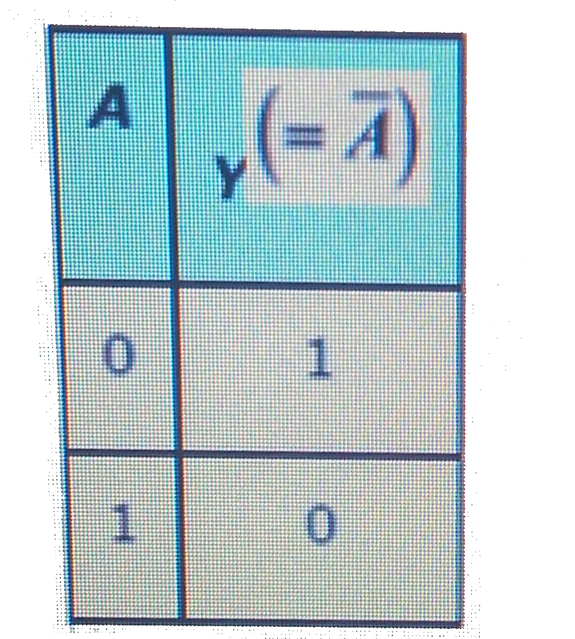
This circuit functions as a NOT gate. The symbol for this logic circuit is shown as:

Topper's Solved these Questions
- BOOK - NCERTCHAPTER - SEMICONDUCTOR ELECTRONICS MATERIALS DEVICES AND SIMPLE CIRCUITSEXERCISE - Exercise15videos
SEMICONDUCTOR ELECTRONICS MATERIALS DEVICES AND SIMPLE CIRCUITS
- BOOK - NCERTCHAPTER - RAY OPTICS AND OPTICAL INSTRUMENTSEXERCISE - Exercise32videos
RAY OPTICS AND OPTICAL INSTRUMENTS
- BOOK - NCERTCHAPTER - WAVE OPTICS EXERCISE - Exercise21videos
WAVE OPTICS
Similar Questions
Write the truth table of AND gate.
View SolutionIdentify the logic operation carried out by the following circuit
 View Solution
Identify the logic operation carried out.
 View Solution
Write the truth table of NAND gate and NOR gate.
View SolutionWrite the truth table for a NAND gae connected as given in the following
 View Solution
Identify the logic operation performed by the circuit given here.
 View Solution
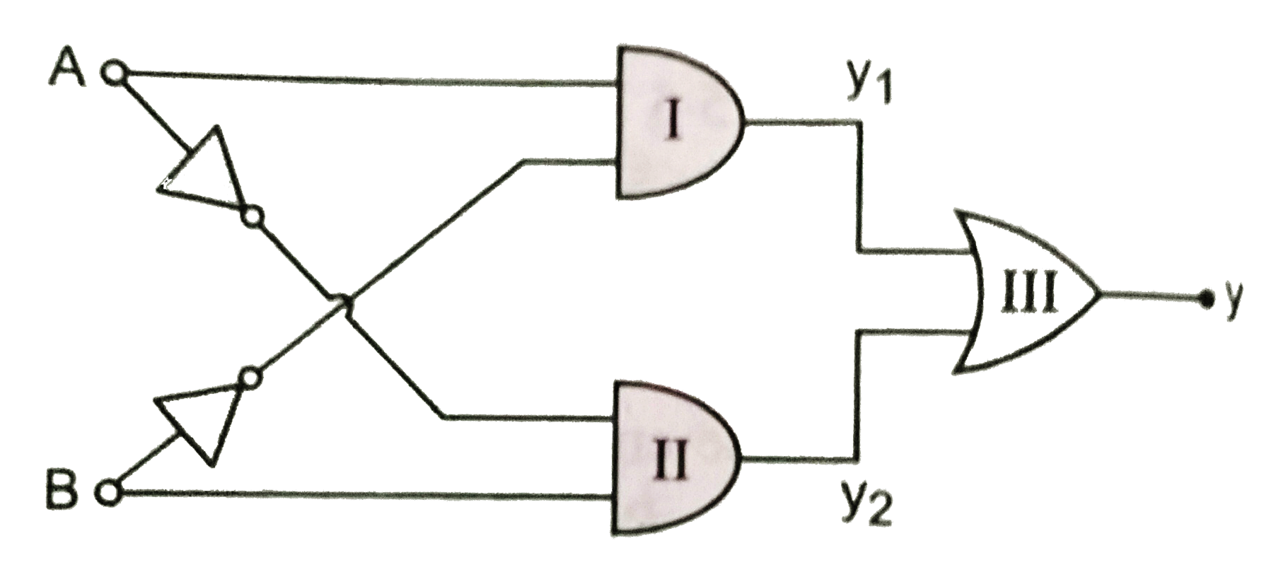
Write the truth table for the circuit shown in Fig.
 View Solution
Write the truth table for the given combination of gates
 View Solution
The truth table for the circuit given in the fig. is:
 View Solution
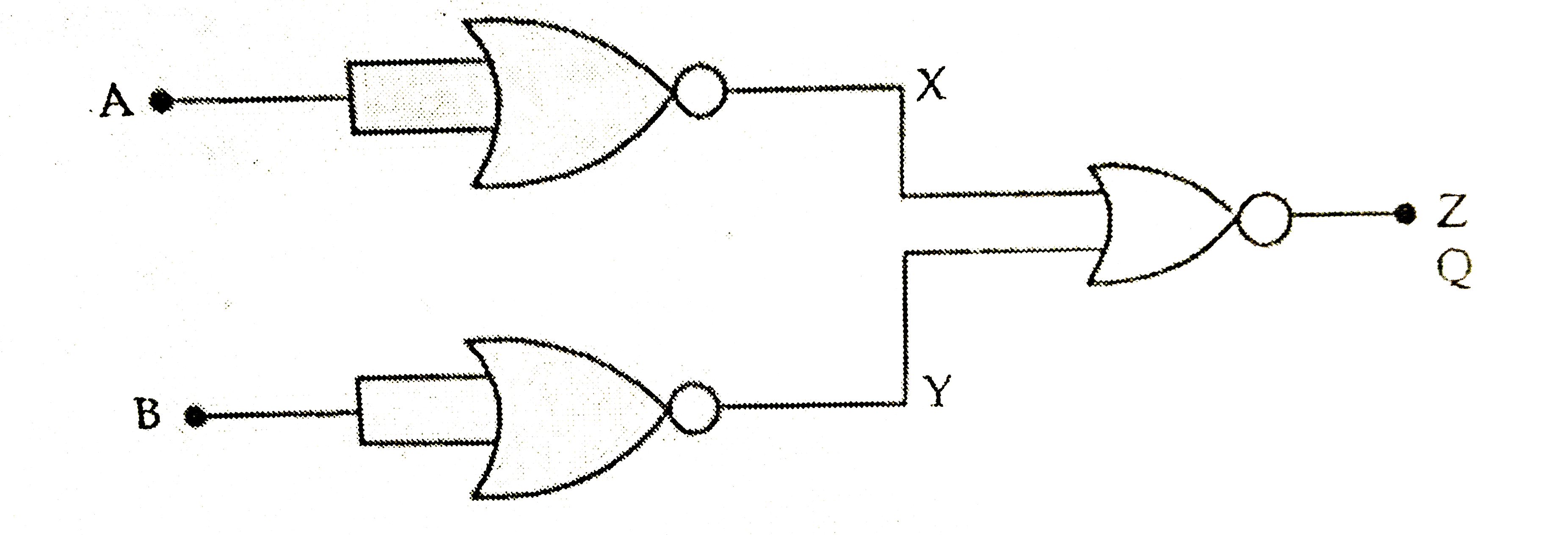
You are given a circuit below. Write its truth table. Hence, identify the logic operation carried out by this circuit. Draw the logic symbol of the gate it corresponds to.
 View Solution

