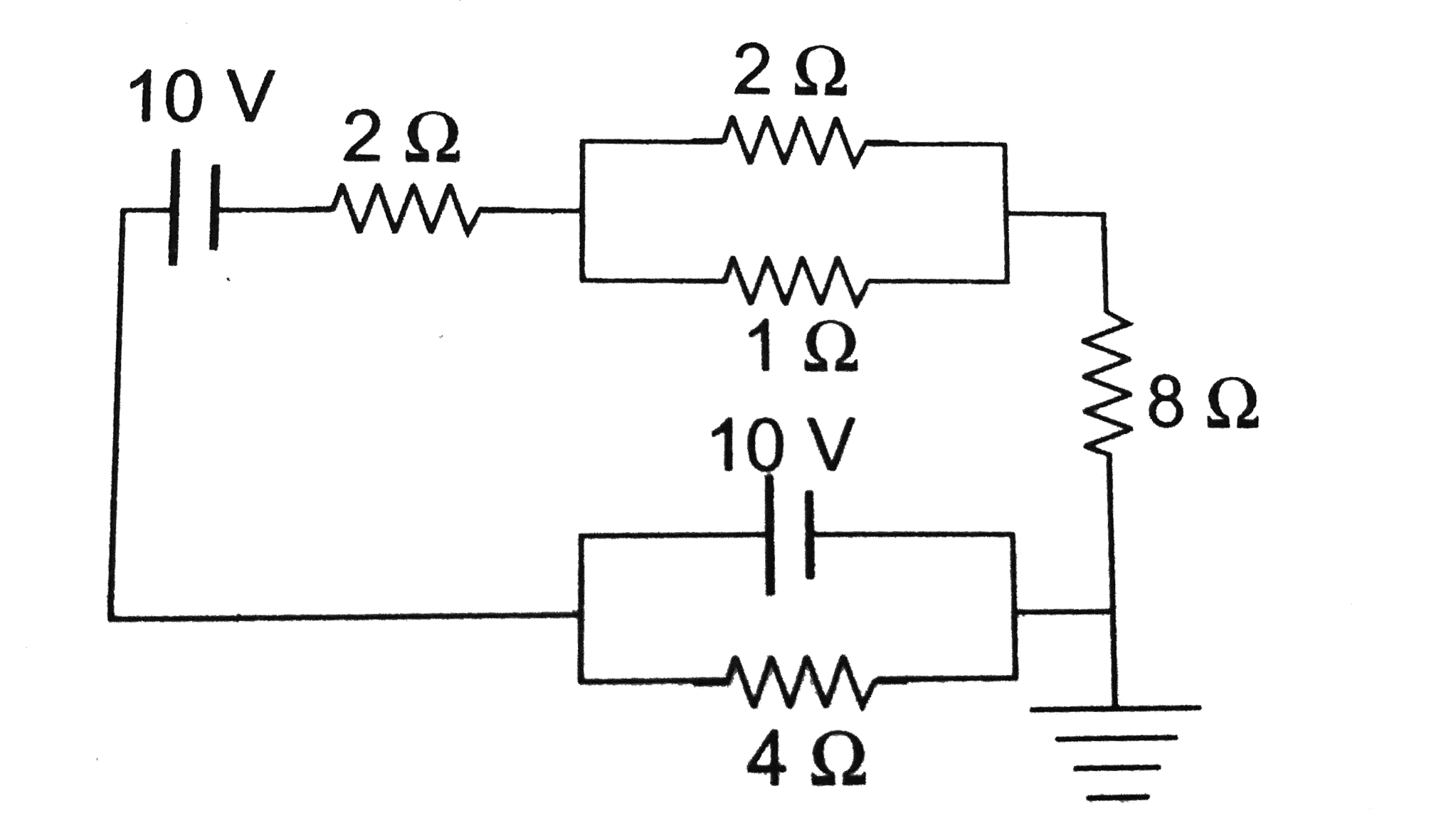
In the circuit shown in the figure, the switch S is initially open and the capacitor is initially uncharged. I1,I2 and I3 represent the current in the resistance 2Ω,4Ω and 8Ω respectively.
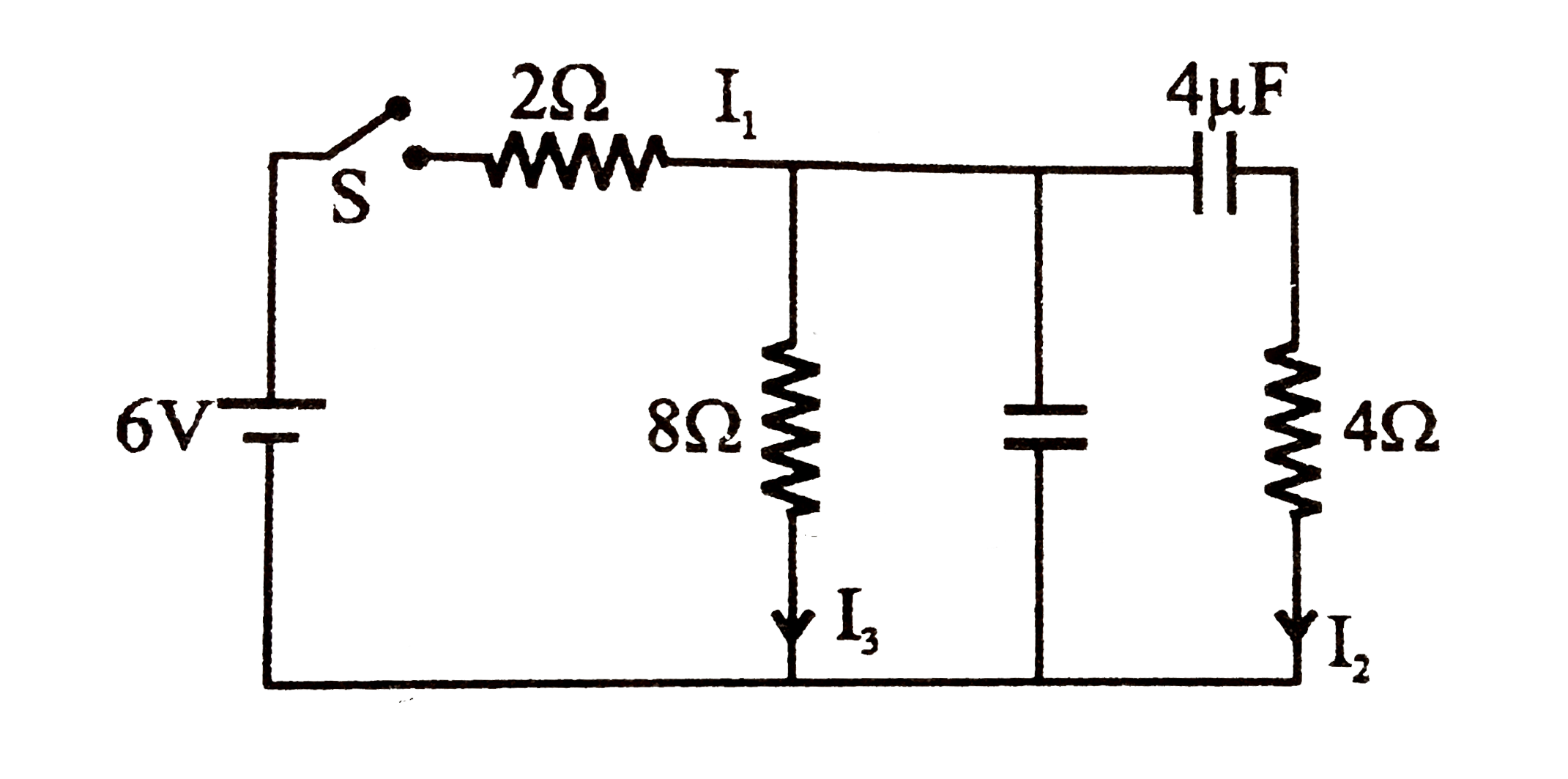
Just after the switch S is closed
I1=3A,I2=3AandI3=0
Just after the switch S is closed
I1=3A.I2=0andI3=0
long time after the switch S is closed I1=0.6A,I∘=0andI3=0
long after the switch S is closed
I1=I2=I3=0.6A
The correct Answer is:B
Step by step video, text & image solution for In the circuit shown in the figure, the switch S is initially open and the capacitor is initially uncharged. I_(1),I_(2) and I_(3) represent the current in the resistance 2Omega, 4Omega and 8Omega respectively. by Physics experts to help you in doubts & scoring excellent marks in Class 12 exams.
Updated on:21/07/2023Topper's Solved these Questions
- Capacitance BOOK - MOTIONCHAPTER - Capacitance EXERCISE - EXERCISE -2 LEVEL (II)
22 Videos
- Capacitance BOOK - MOTIONCHAPTER - Capacitance EXERCISE - EXERCISE -3 LEVEL 1
31 Videos
- Capacitance BOOK - MOTIONCHAPTER - Capacitance EXERCISE - EXERCISE -1
60 Videos
- CALORIMETRY BOOK - MOTIONCHAPTER - CALORIMETRY EXERCISE - EXERCISE - 3 Section - B
4 Videos
- CENTRE OF MASSBOOK - MOTIONCHAPTER - CENTRE OF MASSEXERCISE - Exercise - 4 Level-II
20 Videos
Similar Questions
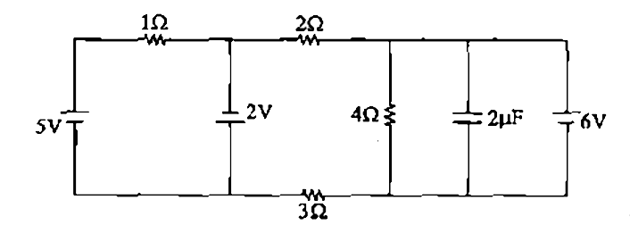
In the circuit shown in figure-3.355, the current in 1Ω. resistance and charge stored in the capacitor are
View SolutionIn the connection shown in the figure the switch K is open and the capacitor is uncharged. Then we close the switch and let the capacitor charge up to the maximum and open the switch again. Then
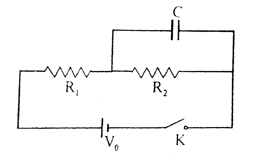
(a) the current through R1 be I1 immediately after closing the switch,
(b) the current through R2 be I3 immediately after reopening the switch, Find I1I2I3 (in ampere−1) (Use the following data: V0=30VR1=10KΩR2=5kΩ)
View Solution
Knowledge Check
In the circuit shown in the figure, the current flowing in 2Ω resistance
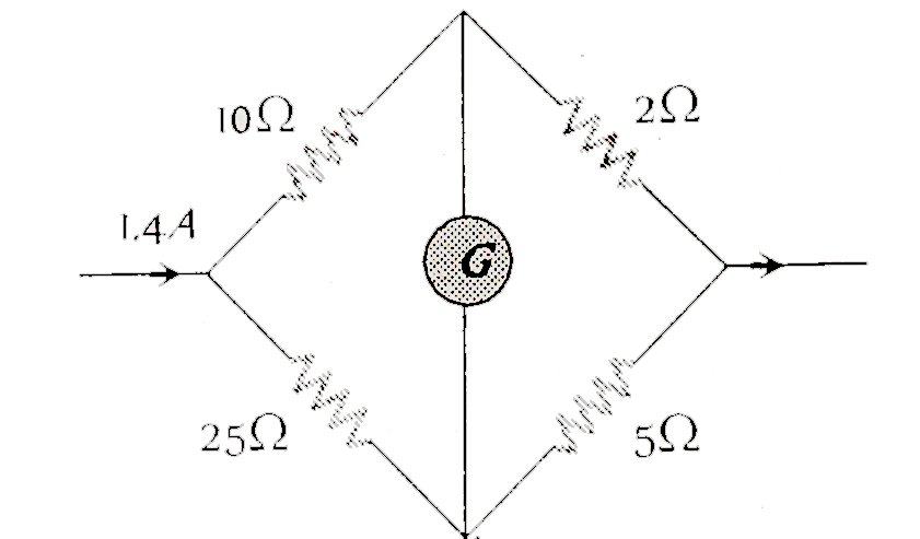 A1.4AB1.2AC0.4AD1.0A
In the circuit shown, the current in 3Ω resistance is
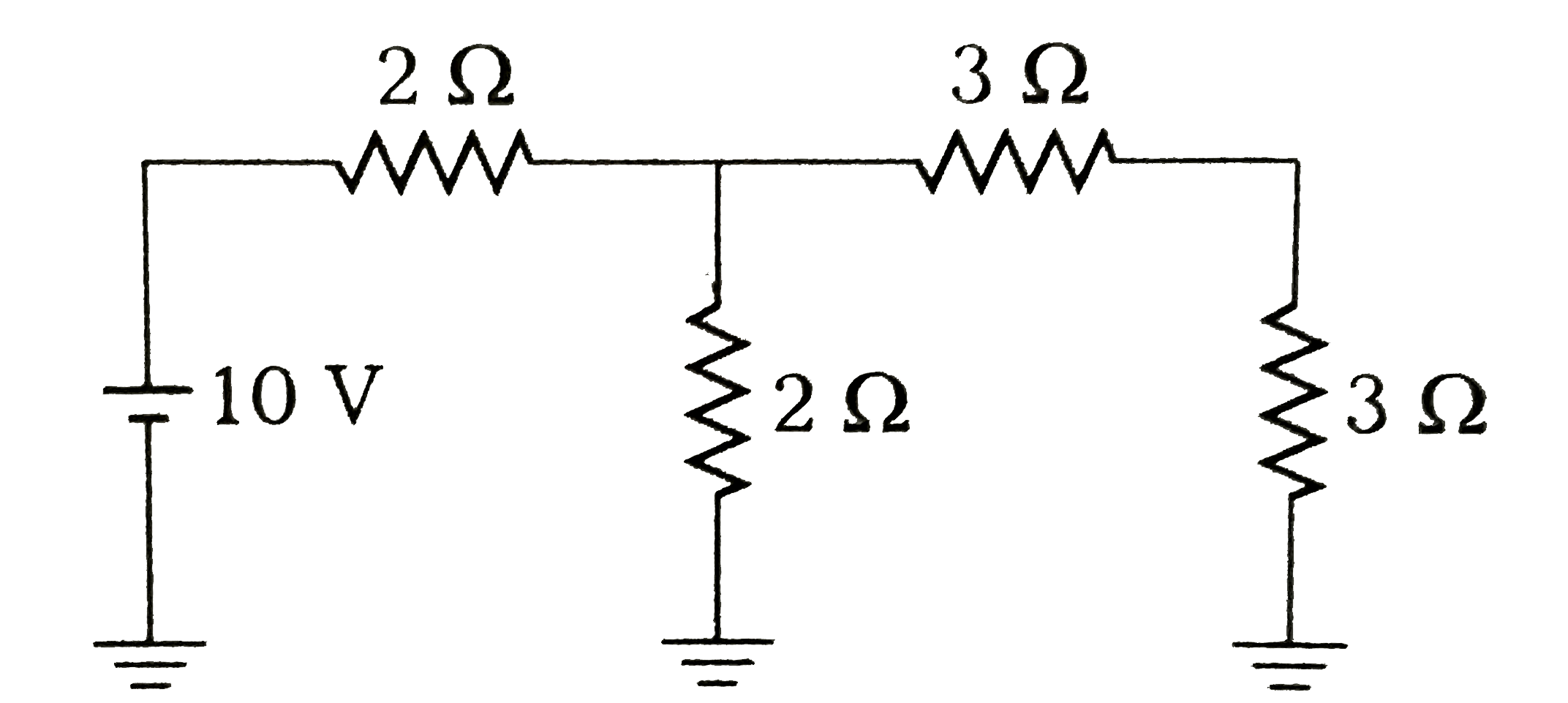 A1AB17AC57AD157A
In the circuit shown, the switch 'S' is closed at t=0. Then capacitor is initially uncharged. Then the current through the resistor R=8Ω at t=0.4×10⁻³sec is (Take e−2=0.135 )
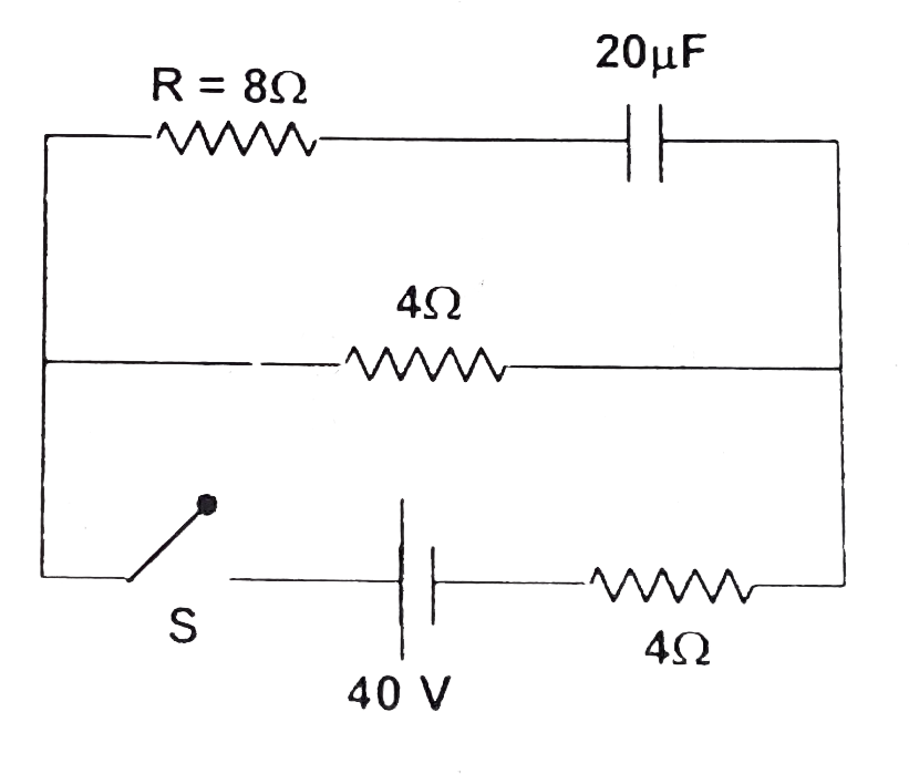 A0.18AB0.27AC0.54AD0.72A
In the circuit shown in figure-3.171, find current in 4Ω resistance.
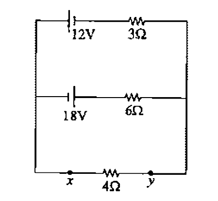
View SolutionIn the circuit shown in figure. 3.82 find the current through battery and current in 8Ω resistances.
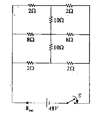
View SolutionIn the circuit shown the currents in 4Ω and 8Ω resistances are
View SolutionIn the circuit shown in the figure The steady state currents i1andi2 in the coils after the switch S is closed are
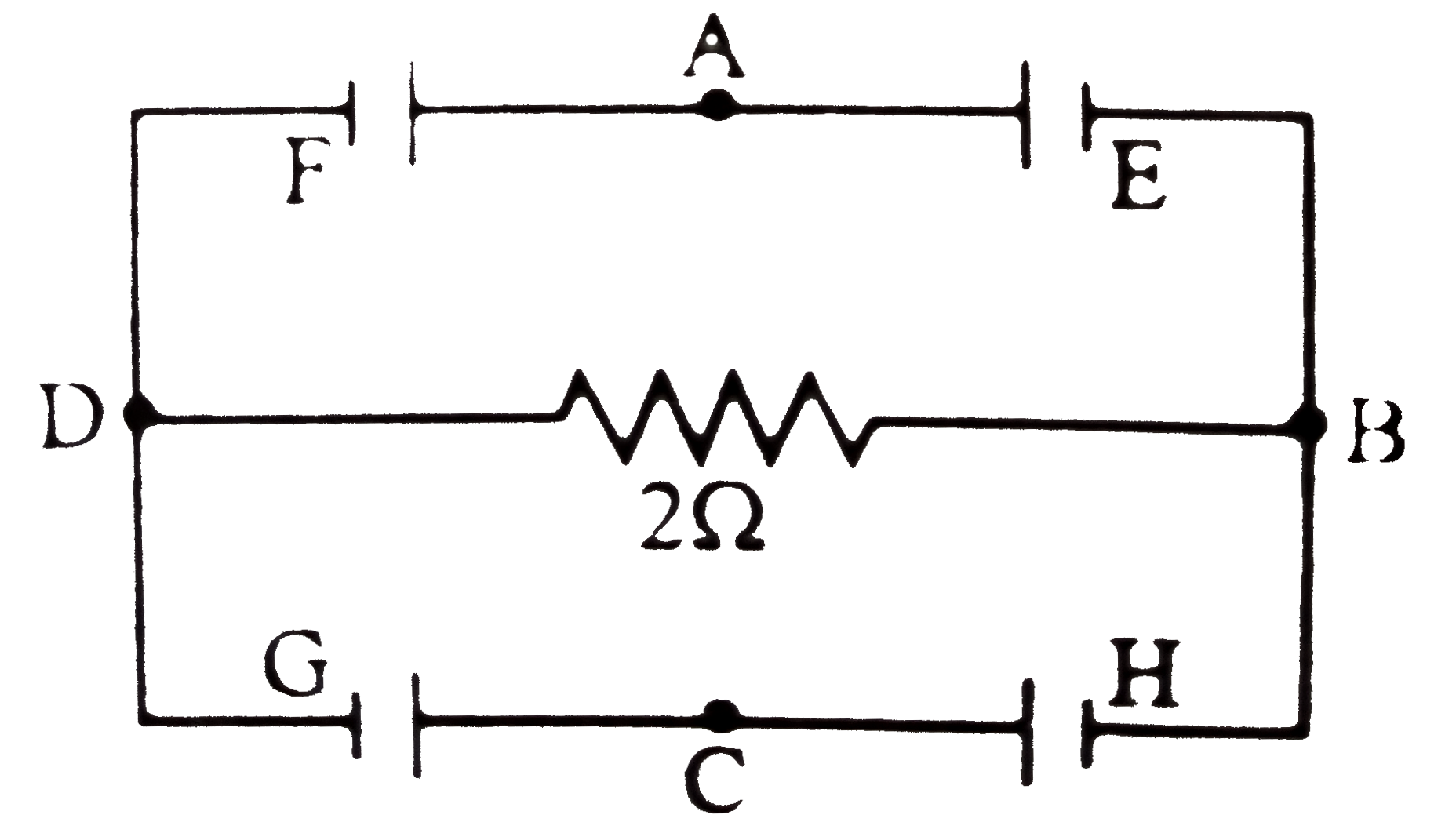
View SolutionIn the circuit shown E,F,G and H are cells of emf 2V,1V,3V and 1V respectively and their internal resistance are 2Ω,1Ω,3Ω and 1Ω respectively.
View Solution
